

Introduction: How to Assemble 8x8x8 RGB LED Cube


About the 8x8x8 LED Cube:
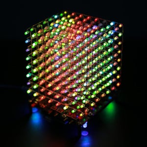
- This is a light cube DIY kit that you need to solder and assemble by yourself in much of patient. The bottom plate comprises a circuit board and component parts. The 512 LED lights make up a stereo space. A variety of cool model showing a three-dimensional effect.
Parameter:
- Work Voltage:DC 4.2V~5.5V
- Work Current:2000mA
- Power Type:MINI USB
- Work Module:Bluetooth/Remote Controller/Button
- Music Type:Bluetooth/U-disk/TF Card/Audio Input
- Work Temperature:-40℃~85℃
- Work Humidity:0%~95%RH
- Size(Installed):100*94*120mm(Different people installed, the height will be slightly different)
Supplies


Step 1: Install 2pcs 20Pin*2 1.27mm Male Pin and 1pcs 10Pin 1.27mm Male Pin

Install 1.27mm Male Pin on Green Main IC Controller Module.
Please pay attention to the installation direction. Connect these 2 pads at the same time.
Step 2: Install 1.27mm Female Pin on Black PCB

Install 2pcs 20Pin*2 1.27mm Female Pin and 1pcs 10Pin 1.27mm Female Pin on Black PCB.
Please pay attention to the installation direction.
Step 3: Install 1pcs Green Main IC Controller Module

Install 1pcs Green Main IC Controller Module on Female Pin which has been install on step 2.
Step 4: Install 1pcs Mini USB Female Socket at J1

Install 1pcs Mini USB Female Socket at J1.
Step 5: Install 2pcs 3.5mm SMD Audio Socket at P2 and P3

Install 2pcs 3.5mm SMD Audio Socket at P2 and P3.
Step 6: Install 3pcs 220uF 16V Electrolytic Capacitor at C1,C7,C13

Install 3pcs 220uF 16V Electrolytic Capacitor at C1,C7,C13.
Please pay attention to the positive and negative pole.The longer pin is positive pin
Step 7: Install 4pcs 5mm RGB LED at Four Corners

Install 4pcs 5mm RGB LED at four corners.
Please pay attention to the positive and negative pole.The longer pin is positive pin.
Step 8: Install 1pcs 10Pin 1.27mm Female Pin on Black PCB

Install 1pcs 10Pin 1.27mm Female Pin on Black PCB.
Step 9: Install 1pcs VS1838B Infrared Receiver

Install 1pcs VS1838B Infrared Receiver on the other side.
Step 10: Install 4pcs Black Button at S2~S5 on the Same Side of VS1838B

Install 4pcs Black button at S2~S5 on the same side of VS1838B.
Step 11: Install 1pcs Red Self-locking Power Switch at S1 on the Same Side of VS1838B

Install 1pcs Red Self-locking Power Switch at S1 on the same side of VS1838B.
Step 12: Install 1pcs 3W 4ohm Speaker and Fixed

Install 1pcs 3W 4ohm speaker and fixed.
Note: The speaker does not distinguish between positive and negative.
Step 13: Install 2pcs Copper Column for Bluetooth Amplifier Module

Install 2pcs Copper Column for Bluetooth Amplifier Module.
Step 14: Install 1pcs Bluetooth Amplifier Module and Fixed by Screw

Install 1pcs Bluetooth Amplifier Module and fixed by screw.
Step 15: Test Main Controller

- Please check to make sure all components are installed correctly and cannot short circuit.
- Connect 5V work voltage form Mini USB female socket.
- The power system works normally if the 4pcs RGB LED flashes automatically.
- Speaker works normally if user can hear ‘du du du’ from speaker.
- Bluetooth Amplifier Module works normally if the phone Bluetooth can search for the Bluetooth device ‘CZL-AUDIO’ and connection succeeded to play music.
- IC Controller Module and Infrared Receiver work normally if user can hear from speaker when press button ‘CH’ on Remote Controller.
- Please increase the input current to be greater than 800mA if animation display is abnormal when increase the volume.
- The main controller is successfully installed if the test is normal.
Step 16: Install 4pcs Copper Pillars and M3 Screw on Acrylic

Install 4pcs Copper pillars and M3 Screw on Acrylic Welding Template.
Step 17: Processing LED Pins

Processing LED pin. Bend the shorter pin to right angle and Bend the longer pin to right angle, but they bend in different directions and positions.
Note: Longer pin is positive.Please be careful not to damage the LED.
Step 18: Place 8*8 3mm RGB LED on Acrylic Templates

Place 8*8 3mm RGB LED on acrylic templates.
The shorter pins of the LED are connected to each other and the longer pins are connected to each other.
Step 19: Fixed All Pins

Fixed all pins. Please align all LED and pay attention to beauty.
Step 20: Test LED by Multimeter

Test LED by multimeter to make sure every LED can turn ON.
If there is an LED that is not lit, please update the replacement LED.
Step 21: Install and Test Other 7pcs 8*8 3mm LED Dot Matrix

Install and test other 7pcs 8*8 3mm RGB LED dot matrix in the same method and test.
Step 22: Remove the Speaker and Bluetooth Module

Remove the speaker and Bluetooth module in order to install the LED to avoid the LED pin damage the speaker.
Then install 4pcs Copper pillars and M3 Screw on PCB.
Step 23: Connect Longer Pin to PCB and Fix
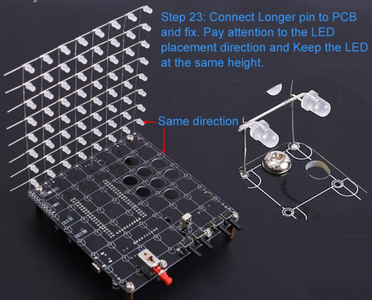
Connect Longer pin to PCB and fix.
Pay attention to the LED placement direction and Keep the LED at the same height.
Step 24: Fix Others 7pcs 8*8 LED 3mm LED Dot Matrix

Same method to fix others 7pcs 8*8 LED 3mm RGB LED dot matrix Keep the LED at the same height.
Step 25: Cut 9pcs 9cm Metal Wire

Cut 9pcs 9cm metal wire as a fixed bracket for LED.
Step 26: Fix 1pcs 9cm Metal Wire on the First Layer

Fix 1pcs 9cm metal wire on the first layer (the Highest layer LED).
It is used to keep the distance of each LED consistent and it can also fix the LED.
Step 27: Fix 1pcs 9cm Metal Wire on the First Layer on Other End

Fix 1pcs 9cm metal wire on the first layer on other end to where the negative.
Step 28: Cut Off Excess Pins

Cut off excess pins.
Step 29: Same Method to Fix Other 7pcs 9cm Metal Wire on Others LED Layers

Same method to fix other 7pcs 9cm metal wire on others LED layers.
Step 30: Connect the Highest Layer LED(the 1st Layer) to Y0 on PCB

Connect the Highest layer LED(the 1st layer) to Y0 on PCB by white wire.
Step 31: Same Method to Connect the 2nd Layer to Y1 and So on for Y2~Y7
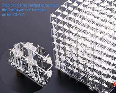
Same method to connect the 2nd layer to Y1 and so on for Y2~Y7.
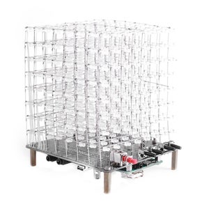
Step 32: Install Speaker and Bluetooth Module

Install speaker and Bluetooth module again.
Step 33: Done

Test and finish.
This colorful 8x8x8 led cube kit is a challenge diy electronic project, it helps us to improve soldering skills and get more joy after it done. Do not hesitate to try it if you'd like to do it! For more interesting led light cube kits, welcome to visist ICStation!


