

Introduction: How to Connect a FT232RL Programmer to the Arduino ATMEGA328 for Uploading Sketches


In this mini Instructable you will learn how to connect the FT232RL chip to the ATMEGA328 microcontroller to upload sketches.
You can see an Instructable on this stand-alone microcontroller here.
Step 1: Parts List
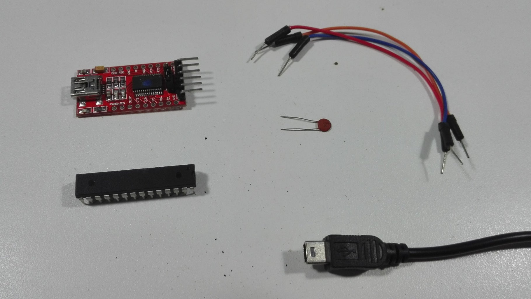
1 x FT232RL chip (got mine here)
1 x ATMEGA328P-PU microcontroller (got mine here)
Wires
USB cable
0.1 uf capacitor
Step 2: Connections for Uploading Sketches


This instructable was made in a hurry and I think the connections in the image are wrong. Should be RX -> pin 3 and TX to pin 2.
FT232RL -> ATMEGA328
DTR via 0.1 uf capacitor > pin 1
RX -> pin 3
TX -> pin 2
VCC -> pin 7
GND -> pin 8
ATMEGA328
Pin 7 (+) -> pin 20 (+)
To upload sketches is the same as usual.
Make sure you select the right port.
If your ATMEGA328 is running at 8Mhz select “Tools → Board” and select “Atmega 328 on a breadboard (8MHz internal clock)”.
If your ATMEGA328 is running at 16Mhz select “Tools → Board” and select “Arduino Uno”.
Step 3: Tip

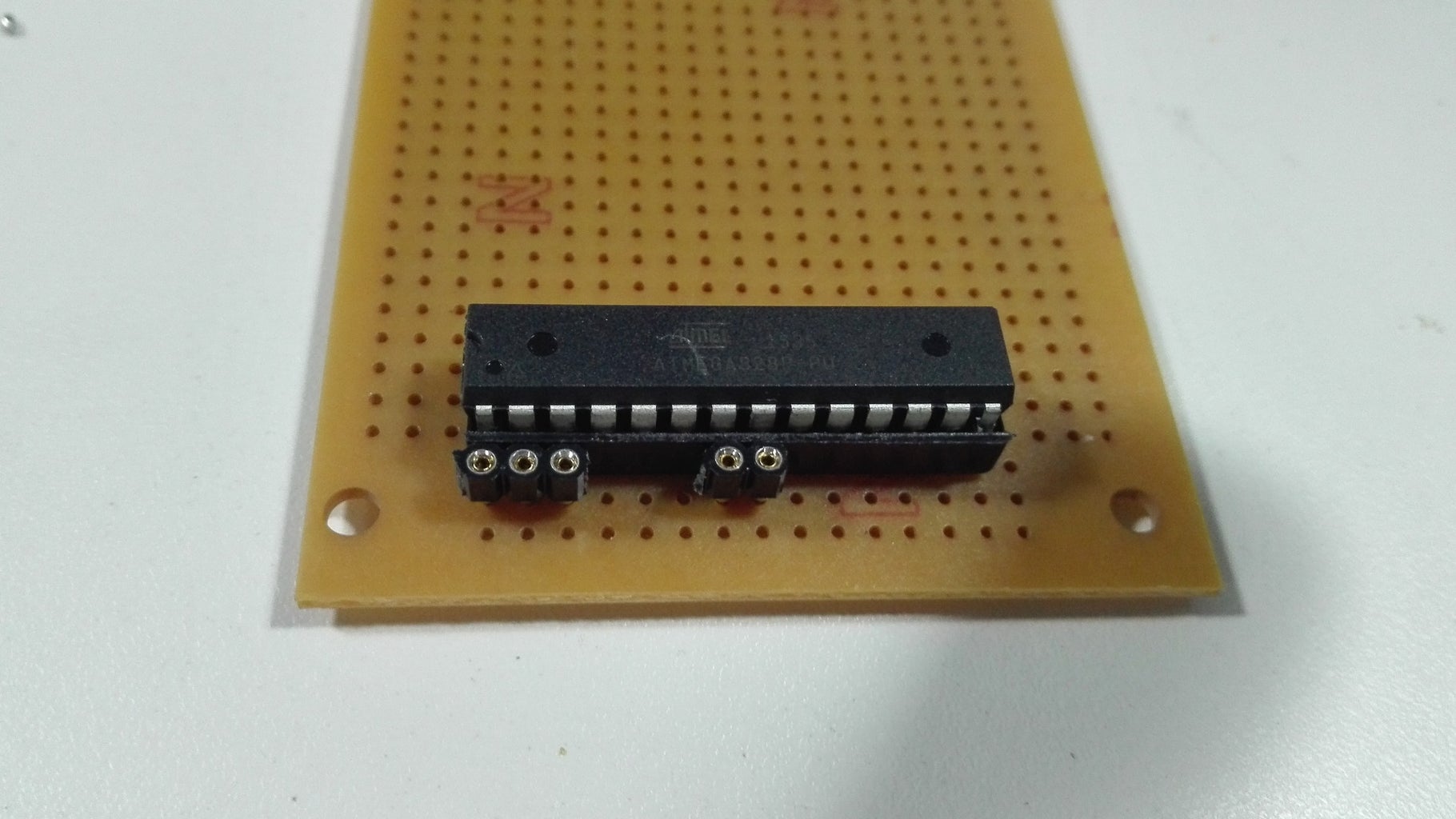

I have soldered the capacitor and the wires to my FT232RL chip so now it's very easy to use.
It is good practise to solder male or female header pins to pin 1, 2, 3 and to + and - so you can still upload and change the program on the microcontroller without having to remove the chip.
Step 4: Final Note
This mini Instructable was a response to a comment made in another Instructable named “$2 Arduino. The ATMEGA328 as a stand-alone. Easy, cheap and very small. A complete guide. “
Did you like this Instructable, click the Favorite button and subscribe.
See you in the next Instructable.
Thanks,
Tom Heylen


