

Introduction: How to Debug Hardware With OpenOCD or PyOCD


If you are having problems in the development of firmware for hardware, it is recommended to use a debugger to see where the problem is in your code and it is easier to give a solution. Dap Cat is a low-cost debugger and programmer that allows you to increase your productivity on your projects.
Story
The Dap-Cat board is a SWD programmer and debugger for ARM Cortex
processors developed by Electronic Cats, being among one of the cheapest programmers in the world, making it an excellent development tool.
Technical information about the board can be found in the manufacturer's repository at the following link.
What are debuggers?
Debuggers, in simple words, are devices that translate the commands sent from the PC (for example, via USB protocol) into a language (for example, SWD or JTAG protocol) that microcontrollers (the peripheral inside the microcontroller that is responsible for loading code and controlling execution to be exact).
Serial Wire Debug
SWD stands for Serial Wire Debug it is the protocol designed by ARM to program and debug its microcontrollers. Since SWD specializes in programming and debugging, it comes with many special features that are generally not available anywhere else like sending debugging information to the computer via the IO line. Also, since ARM made it especially for use in their devices, SWD's performance is usually best-in-class.
SWD pins and architecture
The SWD protocol has only 2 pins:
- SWDIO (serial cable data input-output: the data line) and
- SWCLK (Serial Wire Clock: the clock line)
SWD supports star topology in terms of architecture.
When to choose SWD?
- Let's see some situations where you can choose SWD If your schematics/board design is simple enough to try without JTAG's boundary scanning capability.
- Debugging performance is more important than production testing as your device focuses on research rather than mass production.
- Your product has limitations with regards to dimensions, so space saving by the presence of 2 extra pins on JTAG instead of SWD can be an advantage
- Your hardware design is too complex and you can't route the 2 extra signals to the microcontroller.
Supplies
Step 1: How to Use Dap Cat Debugging?

In this part, I will explain how you
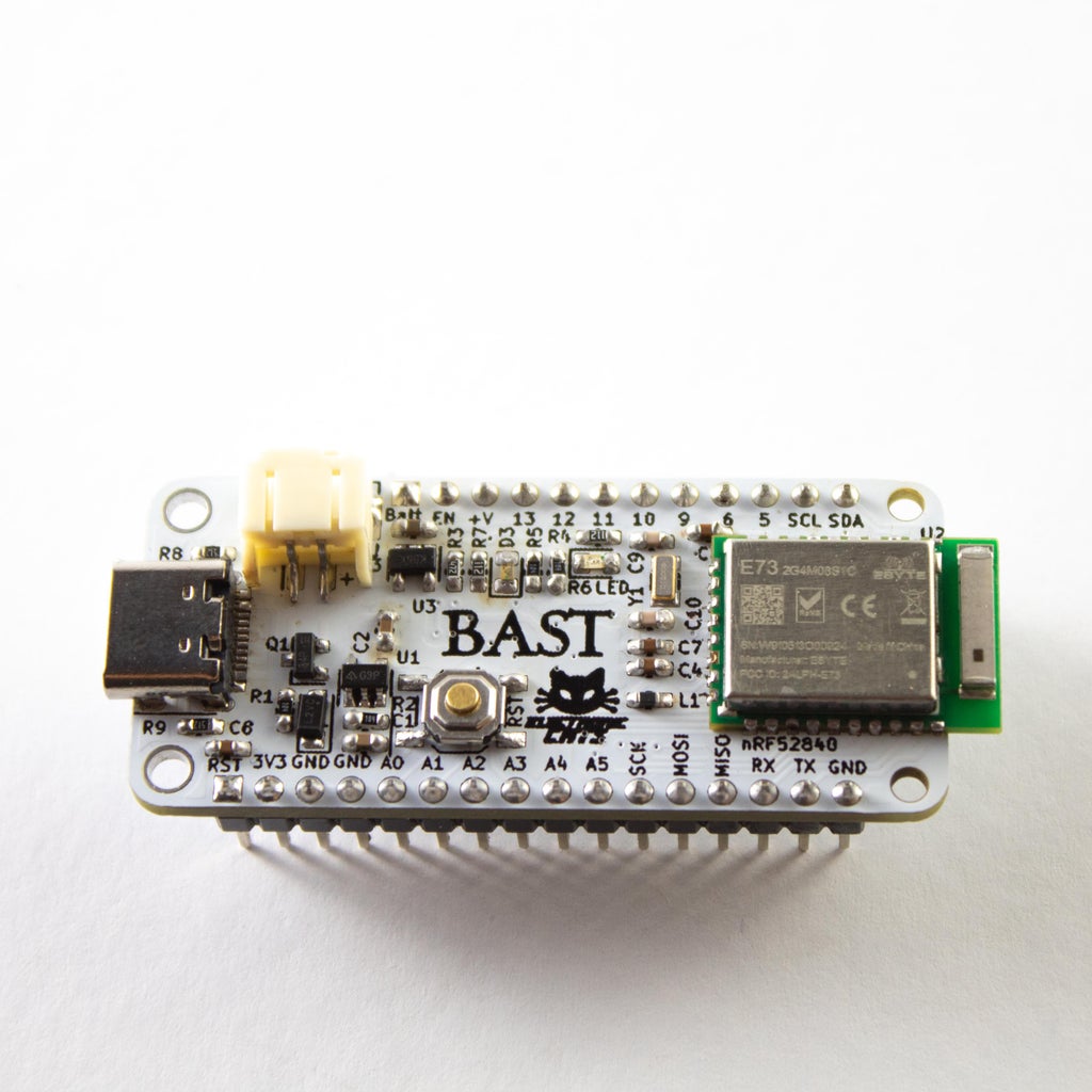
can use it with openOCD and pyOCD, which are free tools that will help you to use this board, and that you can use it with any operating system (Linux, Mac, Windows). This tutorial shows how to use the Dap Cat debugger by loading firmware onto a Bast BLE board with a NRF52840 ARM Cortex M4 microcontroller using SDW communication.
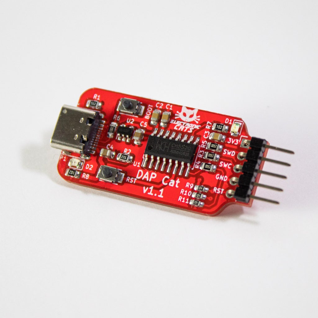
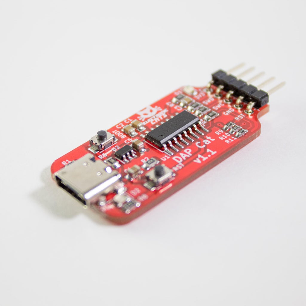
Dap Cat Programmer
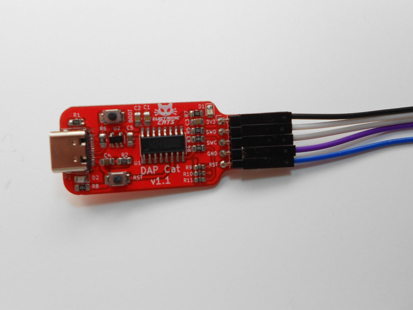
Start by understanding how the Dap Cat programmer and its parts work:
Dap Cat works on the basis of a CH552 microcontroller, has USB-type C, and has two push buttons:
- Boot: This is useful if we want to load the firmware again for its operation or you want to make some modification to the source code and load it later.
- Reset: It will be used to restart the Dap Cat programmer.
It also has 5 male pins where you will find for SDW communication, the name of the pins and a brief description are listed below:
- Pin 3v3: The reference voltage will be connected to this, being a value no greater than 3.3 volts.
- SWD
- SWC
- GND: This pin is connected to GND of the chipset to be debugged or programmed.
- Rst: This pin will help us to restart the chipset or board to which firmware is being loaded.
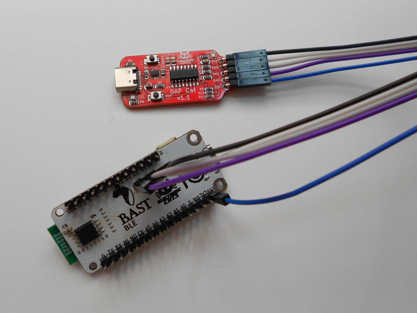
The following image shows how the Bast BLE card is connected to the Dap Cat debugger using 5 dupont wires.
Dap Cat with openOCD + GDB
In order to use the Dap-Cat programmer, it is important to install third-party open software, these programs will allow the board to be used as a debugger and programmer.
- Openocd Open On-Chip Debugger
- ARM GDB
It is necessary to install the two software mentioned above, follow the instructions on their installation page depending on your operating system.
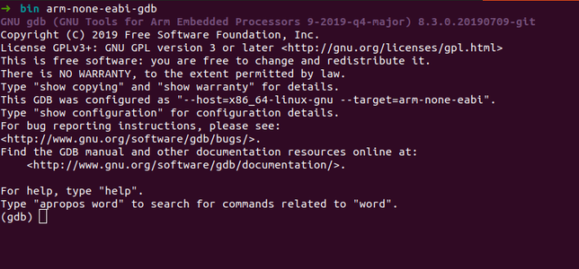
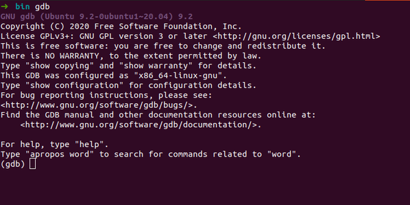
Step 1: Open GDB
Once GDB has been installed correctly, it can be used in your operating system console by typing the gdb command. It is displayed as follows:
In order to debug our code it is important to do it as follows:
Open the console at the address where the file that you are going to upload to the chipset is located and write the following command:
arm-none-eabi-gdb code.elf
"code.elf" is the name of the file that you are going to upload to the chipset. The result in the console is shown in the following image.
Step 2: Open openOCD
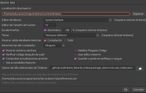
In another console, openOCD will open Arduino has openocd in its configuration and uses its IDE to program the chipsets that are configured.
To facilitate, we will use the openocd configuration that Arduino uses as a base and that it provides us with a large number of chipsets, so it is important to identify the default path that the Arduino folder has.
arduino/50/.arduino15/packages/arduino/tools/openocd/0.9.0-arduino/bin
In that path is where the console will open, which we will use to work and load the appropriate configuration. When working with openOCD it is important to call it in the console with the configuration file "openocd.cfg", this file has been added in the part of code to download, you can see in the following code:
source [find interface/cmsis-dap.cfg]
transport select swd
set CHIPNAME nrf52840
source [find target/nrf52.cfg]
# did not yet manage to make a working setup using srst
#reset_config srst_only
#reset_config  srst_nogate
adapter srst delay 100
adapter srst pulse_width 100
init targets
reset halt
To start openOCD it is common to use the console or terminal of your O.S.
Depending on your operating system, you must call with administrator permissions to allow you to establish communication with the Dap Cat board.
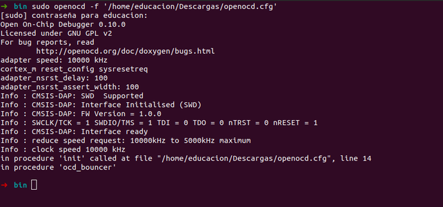
The following example shows the command used for Linux:
sudo openocd -f /home
/home refers to the location where the "openocd.cfg" file is located If you have started correctly you will see the following message:
Step 3: Flash firmware on chipset
Finally, it only remains to communicate internally GDB with openOCD, for this the following command is used in the GDB console:
target remote localhost:3333
Once communication has been achieved, the following message will appear:
arm-none-eabi-gdb code.elf (gdb)
target remote localhost:3333
Remote debugging using localhost:3333 ...
(gdb)
In order to load the firmware and start debugging in the console, write the following command:
(gdb) load
The firmware will begin to load onto the chipset and the following message will appear:
arm-none-eabi-gdb example.elf
(gdb) target extended-remote localhost:3333
Remote debugging using localhost:3333...
(gdb) monitor reset halt...
(gdb) load
Loading section .vectors, size 0x100 lma 0x20000000
Loading section .text, size 0x5a0 lma 0x20000100
Loading section .data, size 0x18 lma 0x200006a0
Start address 0x2000061c, load size 1720
Transfer rate: 22 KB/sec, 573 bytes/write.
(gdb) continue
Continuing....
At that moment the code will start running on your chipset.
Step 2: Dap Cat With PyOCD
pyOCD is an open-source Python package for programming and debugging Arm Cortex-M microcontrollers using multiple supported types of USB debug probes. It is fully cross-platform, with support for Linux, macOS, and Windows.
A command-line tool is provided that covers most use cases, or you can make use of the Python API to enable low-level target control. A common use for the Python API is to run and control CI tests. Upwards of 70 popular MCUs are supported built-in. In addition, through the use of CMSIS-Packs, nearly every Cortex-M device on the market is supported.
For more detailed information, refer to the pyOCD GitHub repository.
Installing
The latest stable version of pyOCD may be installed via pip as follows:
pip install -U pyocd
If you are using Windows is necessary to install the libusb manual way, download libusb from libusb.info and place the .dll file in your Python installation folder next to python.exe.
Make sure to use the same 32- or 64-bit architecture as your Python installation. The latest release is available on GitHub; download the .7z archive under Assets. Use the library from the VS2019 folder in the archive.
Basic Usage
The pyocd command line tool gives you total control over your target with these subcommands:
- gdbserver: GDB remote server allows you to debug using gdb via either GNU MCU Eclipse plug-in or the console.
- flash: Program files of various formats into flash memory.
- erase: Erase part or all of an MCU's flash memory.
- pack: Manage CMSIS Device Family Packs that provide additional target device support.
- commander: Interactive REPL control and inspection of the MCU.
- list: Show connected devices.
Target support
When pyOCD connects to a target, it needs to know what type of target it is controlling.
To see the available target types you can run:
pyocd list --targets
Programming
The flash programming may be the most frequently used option of Dap Cat pyOCD offers a variety of commands for programming with different options.
You can get additional help by running:
pyocd erase --help
pyocd flash --help
The following commands demonstrate how to flash/erase a Bast BLE with nRF52840-based target:
To erase all of the target flash:
pyocd erase -t nrf52840 --chip
To flash the target with .hex-format firmware:
pyocd flash -t nrf52840 Sample.hex
To flash the target with a plain binary:
pyocd flash -t nrf52840 --base-address 0x1000 Sample.bin
The --base-address option is used for setting the address where to flash a binary. Defaults to start of flash.
Debugging
pyOCD contains a GDB remote server which allows you to debug using gdb.
You can get additional help by running:
pyocd gdbserver --help.
You will be able to execute the following in order to start a GDB server:
pyocd gdbserver -t nrf52840
In the second terminal window, connect to the GDB server and load firmware by running:
$ arm-none-eabi-gdb application.elf
target remote localhost:3333
load
monitor reset
With this, you will be able to see each of the instructions in your code to be able to debug.

Participated in the
PCB Challenge


