

Introduction: PWM(Pulse Width Modulation) Remote Control Using Arduino and HT12E & HT12D


Hey! Guys How You all doing! Today I am Back With Another Cool and Very useful INSTRUCTABLE .
I am pretty sure if you guys ever tried of making remote controlled vehicles like drone or robot then you must have come across the word "Remote Controller" , But the thing is if we Talk about DRONE then you Have to buy those expensive Remote Controllers like this
it costs Rs.4650 Or 72.2061 US Dollar which is very expensive , for just a remote Controller
The Cheapest Remote Controller present in Market costs Rs2000 or 31.05 US Dollar. Still it is costly for Making Small Drones.
So what Can We Do in order to Deal with This Problem,
DON'T WORRY!, GUYS I have a solution for it......
You can Make Your Own Remote Controller with Just few cheap & easily Accessible Items
Before i Tell You how You can Make it Just have a look at My professional Video and Trust me it will Really Help You out in Building your Remote Control. I have explained each and every thing in Video
*Features Of My Remote Control*
(1)10K Rocker Potentiometer or Simple Potentiometer Supported
(2)Response Time Less Than 5 miliSeconds.
(3)Smart Switching Technology
Step 1: MATERIALS REQUIRED


(1)Two 10K Potentiometer
(2)433Mhz (ASK) RF Transreciever
(3)HT12E & HT12D
(4)Two USB to Serial Cable
(5)Jumper Wires
(6)Two Arduino Uno
Step 2: Wiring Up Transmitter Side


Before Wiring up everything
must check whether transmitter and Reciever are working fine for reference see this
Wireless Transmitter and Receiver using ASK RF Module
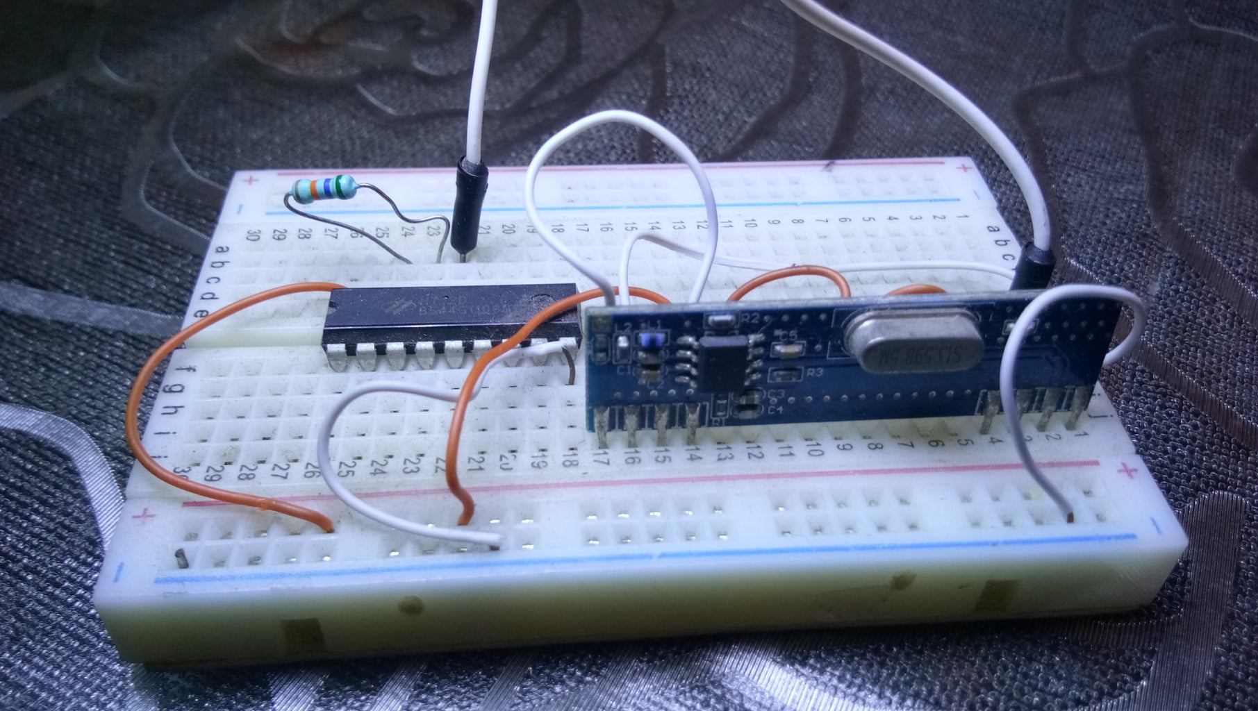
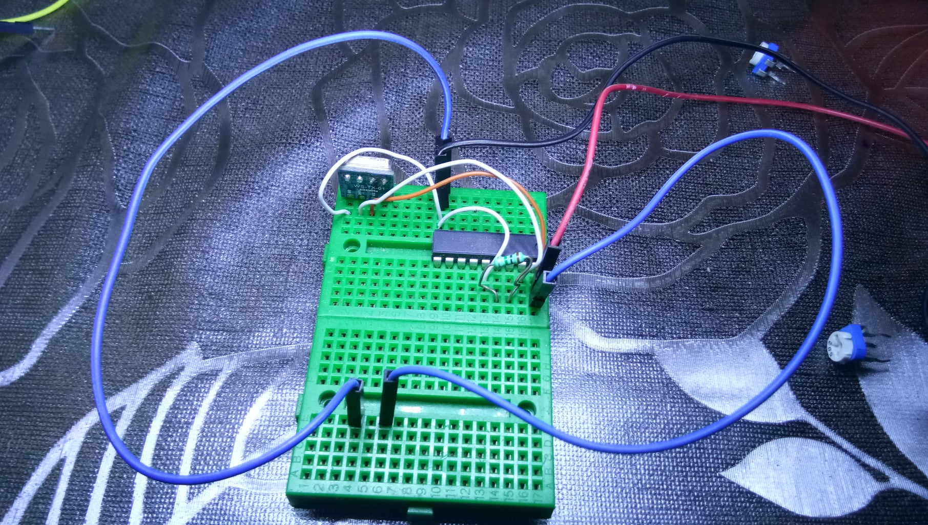
(1)Now connect red wire and Black wire to Vcc and Gnd of HT12E Respectively
(2)next,Hook two blue wires one to vcc of HT12E and another to Gnd(ground) of HT12E
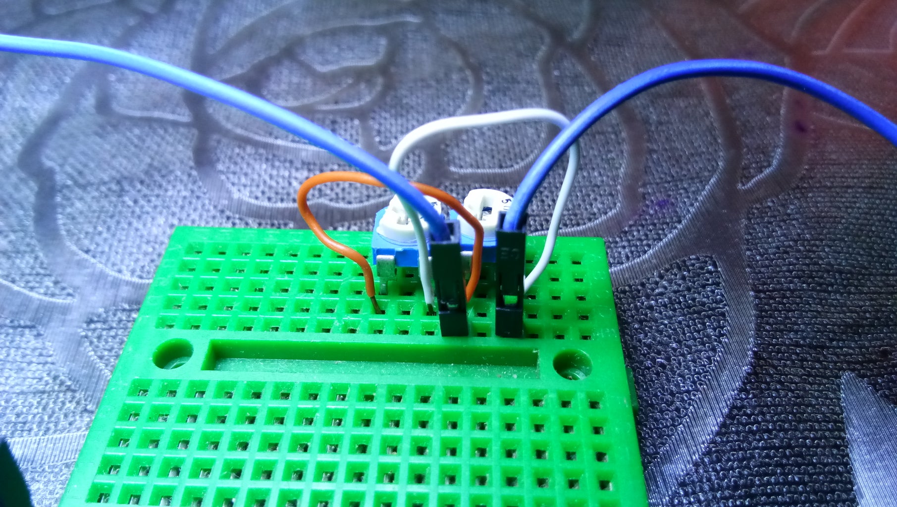
(3)insert two potentiometer into breadboard and power up them using two blue wires attached in the above step
(4)Now Connect Two Yellow wires to middle pin of both the Potentiometer
(5)Next connect First Potentiometer Yellow Wire to Analog 0 pin and Second Potentiometer Yellow Wire to Analog 1
(6)Now, connect: white jumper wire 1 to HT12E AD0
white jumper wire 2 to HT12E AD1
white jumper wire 3 to HT12E AD2
white jumper wire 4 to HT12E AD3
(7)Next, Connect Red wire and Black wire to Vcc(5volts) and Gnd(ground) of Arduino Uno [as connected in Step one]
(8)Now , Final step: connect other end of 4 white wires according to the order below. [refer to step 6]
white jumper wire 1 to HT12E AD0 :Digital Pin 3 Of Arduino Board
white jumper wire 2 to HT12E AD1 :Digital Pin 4 Of Arduino Board
white jumper wire 3 to HT12E AD2 :Digital Pin 5 Of Arduino Board
white jumper wire 4 to HT12E AD3 :Digital pin 6 Of Arduino Board
Transmitter Part Done!
Step 3: Reciever Side
Now, Reciever side Wiring is Same as transmitter except the fact it has no potentiometer input, it has just four wires connected as Following
D0 of HT12D : Digital Pin 3 of Arduino
D1 of HT12D : Digital Pin 4 of Arduino
D2 of HT12D : Digital Pin 5 of Arduino
D3 of HT12D : Digital Pin 6 of Arduino
for Complete Information Watch My Video.
Step 4: Download Transmitter and Reciever Code for Arduino
This Remote Control Requires Two Arduino Board,one for Transmitter and another for Reciever
Download Here:-

Participated in the
Invention Challenge 2017


