

Introduction: How to Make a Binary Clock With 20 LEDs and an Arduino


Hey guys, Welcome to Being Engineers. It has been long time since we posted any tutorial on this channel. Please excuse us for that. But we uploaded some videos in our youtube channel in this time. So you can check you those videos if you want. Channel link is given in the later part of this post.
In this video I will be showing step by step, how to make a binary clock. Yeah, I know. There are thousands of tutorials on internet telling the same thing. But this binary clock that we are going to make here is somehow different from the rest of it. This binary clock will be made using a technique called charlieplexing. we will be using around 20 leds to visually represent the time to us. And if you are familiar with the arduino board then you know that an Atmega328pu based boards doesn't have that many digital pins to control 20 leds at once. So the obvious solution that comes out of this is multiplexing. In multiplexing we could have used matrix formation where we would need around 10 pins to control 20 leds in a formation of 4X6. But we will be going more deep and will use only 5 pins out of the arduino to control 20 leds. This technique is nothing but charlieplexing. With these few pins in use you can attach more components, sensors or relays on the unused I/O pins to add more functionality.
This will be a single tutorial, but on youtube there are 2 videos explaining the whole thing. The first video consists of the detailed explanation of the charlieplexing concept and how to use it in different scenarios. The sequel is the detailed binary clock making video. If you don't want to read this tutorial, then you can also watch the videos to get the idea.
1st video -
2nd video -
If you haven't subscribed to our channel till now, then please do it. Also don't forget to follow us on social medias.
Channel link - https://www.youtube.com/c/being_engineers1
So that's it. Enough of this boring introduction. Let's start this tutorial from here.
Step 1: Know About Charlieplexing


Charlieplexing is the main concept on which the whole build stands. So you need to understand what this is and why we are using it. In general term you can say it is a type of multiplexing by which you can use only N numbers of I/O pins to multiplex n(n-1) numbers of leds. But it's tough to make it understandable in writing. I will suggest you to watch the 1st video to understand the concept well and then start from the step 2.
Step 2: Gather All Required Items
The items that you will need are the following -
- 20 X 3mm leds (colour as per your choice)
- 5 X 100 ohm quarter watt resistor
- 1 X Arduino nano or Arduino pro mini
- 1 X DS1307 IC
- 1 X 8 pin DIP IC socket
- 1 X 32.768Khz crystal oscillator
- 2 X 10k ohm quarter watt resistor
- 1 X 7805 voltage regulator
- 1 X 10uf electrolytic cap
- 1 X DC female adapter
- 1 X CR2032 3V coin cell with battery holder
- Male and female jumper headers
- Veroboard
- 9V - 12V DC supply
Except these you will need all relevant soldering equipment and some silver copper wires to make bridges.
Step 3: Design the Circuit and Ordering the PCB


This PCB is ordered from : JLCPCB
First of all you need 20 leds arranged and soldered properly. If you have watched our previous video then you know the soldering is tough for this type of work. Even if it was possible I was reluctant to do it, also my soldering skill is horrible to be frank. So I logged in to Easyeda and made a simple circuit with all those leds and 5 current limiting resistors for 5 input lines. Then I converted the circuit to PCB and did the routing by the router tool. With easyEDA this kind of work gets a lot easier. Once the PCB design is done, I ordered the pcbs from JLCPCB and received the package in 15 days.
The led arrangement and the PCB layout is given in the attachment. If you are comfortable with soldering then try making this plot on a veroboard.
Step 4: Solder the Leds on Board With the Current Limiting Resistors
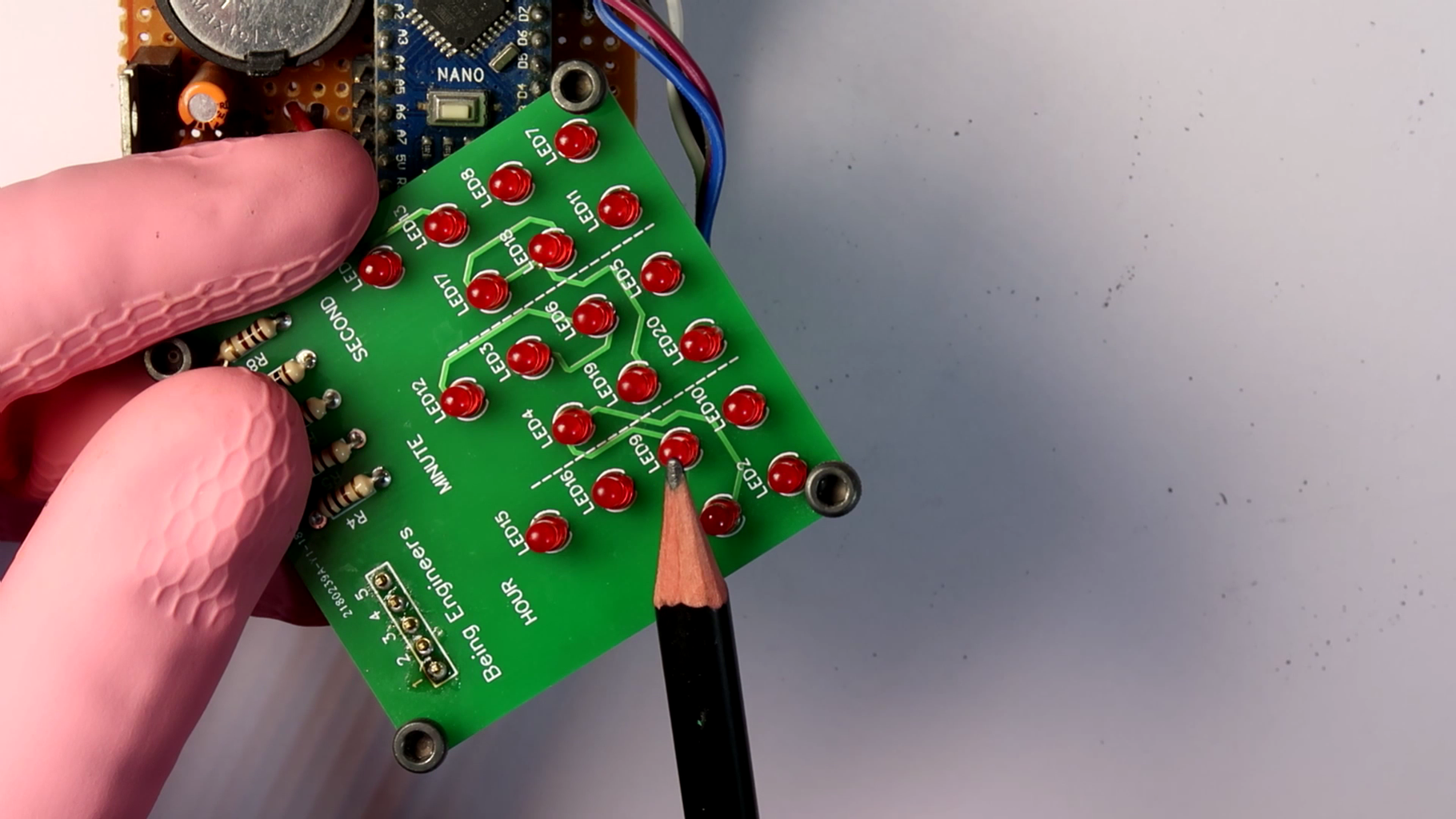
If you have made this circuit by hand soldering then this step is irrelevant to you. But those who made their PCB from manufacturer, they need to solder those 20 leds in correct formation. After that add five 100 ohm resistors in series with each branch at the designated spot. Then solder five male headers at the labeled area where jumpers will be attached later on.
Step 5: Design the Controlling Circuit and Make the PCB


Now as the main clock is ready, it's time to think about the controlling circuit. I used a Arduino nano for this project. Pro mini would have been more appropriate but at that moment I didn’t have one. Theoretically any microcontroller which has 5 I/O pins and supports I2c communication protocol can do the job. But for simplicity let's go with arduino.
Then we need a RTC IC, which can precisely count the time for us. I choose the dependable DS1307 IC for this purpose. for better accuracy, in long run I will recommend to use DS3231 IC in place of DS1307.
To power the DS1307 IC constantly, a 3V battery will be there in the circuit. And to power up the whole system including arduino, leds etc.. you will need a DC supply which can give output at 9V - 12VDC. Then this DC will be stepped down to 5V by a 7805 regulator.
The circuit diagram is given in the pictures.
Make the whole circuit on a veroborad and then go to the next step.
Circuit Diagram - https://drive.google.com/open?id=1Gz_ibihlHpFXP9s...
LED Sequence diagram - https://drive.google.com/open?id=1_Fxu3DarSYr4BHT...
Step 6: Complete the Hardware Built and Tidy Up the Connections

In this step we will complete the build. First of all drill four M3 size holes in both the pcbs. Then by putting some stud in between the PCBs raise up the platforms to make some room to fit in the jumpers later on.
Connect the jumpers in between the arduino and the other PCB. Insert the 3V cell in battery holder.
At last double check if all soldering is done correctly and nothing is shorted by the screws. when done file the edges and make it little more presentable.
Step 7: Set the Current Time and Date in the RTC Module

Now it's time to set the correct time and date into the RTC ic i.e. DS1307 for this case. To do that connect the arduino to a computer with USB cable and open Arduino IDE.
Open the following code in IDE. change the time and date variables to the correct ones and upload the code with the proper board and serial port selected. When uploading the code the DS1307 IC should be powered constantly by the 3V cell. Otherwise as soon as the USB cable is disconnected, The IC will stop counting the time further.
Arduino set time code - https://drive.google.com/open?id=1opDZntEXH-t45GY...
Step 8: Upload the Code in the Arduino
With the USB cable connected again open the arduino IDE. Run the following code and upload the same to the arduino.
Binary clock code - https://drive.google.com/open?id=1Ce67jWiYz5Tqj_u...
Step 9: It's Almost DONE!

The project is almost complete now. Just unplug the USB cable and plug in a DC supply of 9v-12v to the Dc adapter and the clock should start immediately.
That's it. Hope you have liked this project. If yes, then don't forget to visit our channel and subscribe us.
Thanks again for following this tutorial.
peace :)

![Tim's Mechanical Spider Leg [LU9685-20CU]](https://content.instructables.com/FFB/5R4I/LVKZ6G6R/FFB5R4ILVKZ6G6R.png?auto=webp&crop=1.2%3A1&frame=1&width=306)


