

Introduction: How to Read Arduino Sensor Data on Android App Using Bluetooth


The concept of controlling or executing a task on Arduino with a mobile phone over Bluetooth has gained enormous popularity in the recent years. Makers and developers started to create custom applications for this purpose using easy to develop software such as MIT APP inventor. Most of these applications were utilized for sending one way information. This Instructable is aimed at demonstrating a simple method to read an Arduino's sensor data on an Android app based on the sensor selection made by a user (Hence, a two way communication).
To consider an example, three distinct sensors are used in this project:
- Light Dependent Resistor (LDR)
- Potentiometer
- Infrared (IR) Sensor
Communication between the mobile phone and the Arduino is supported by HC-05 Bluetooth module.
Step 1: Materials Required
- Arduino UNO x 1
- USB cable. x1
- Breadboard x 1
- Wires (Male to Male) (Male to Female)
- 1Kohm Resistor x 1
- Light Dependent Resistor (LDR)x 1
- 1Kohm Potentiometer x 1
- Infrared Sensor (IR sensor) x 1
- HC-05 Bluetooth Sensor x 1
- Android Mobile Phone x 1
Step 2: Connecting LDR and Resistor to Arduino
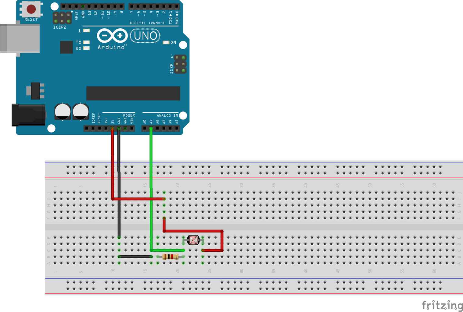
LDR
LDR is expanded as Light Dependent Resistor. Depending upon the intensity of light projected to the surface of an LDR, it changes its resistance value. The value of resistance changes from few ohms under sufficient light condition to few Mega Ohms under dark conditions.
Circuit Connections:
- Connect one leg of the LDR to VCC (5V) on the Arduino via the breadboard (5V line) as shown in the figure.
- Connect the other terminal of the LDR to the Analog pin 1 (A1) on the Arduino.
- Connect one pin of the 1Kohms resistor to one terminal of LDR which is connected to pin A0.
- The other terminal of resistor is connected to the ground of the Arduino via the breadboard(GND line).
Step 3: Connect Potentiometer to the Arduino

Potentiometer:
Potentiometer is a resistor that can change its value. It has three terminals, i.e., two pins at the bottom and one pin at the top. The two pins at the bottom are connected with VCC and GND in any order since potentiometer is a resistor. The pin at the top of the potentiometer is connected with the wiper of the potentiometer. Hence, it outputs a fraction of the supplied VCC voltage.
Circuit Connection:
- Place the potentiometer on the breadboard.
- Connect the wiper pin to A2 pin of the Arduino using a connecting wire
- Connect one of the bottom pins of the potentiometer to the 5V line using a connecting wire.
- Connect the other bottom pin of the potentiometer to the GND line using a connecting wire.
Step 4: Connect IR Sensor to the Arduino
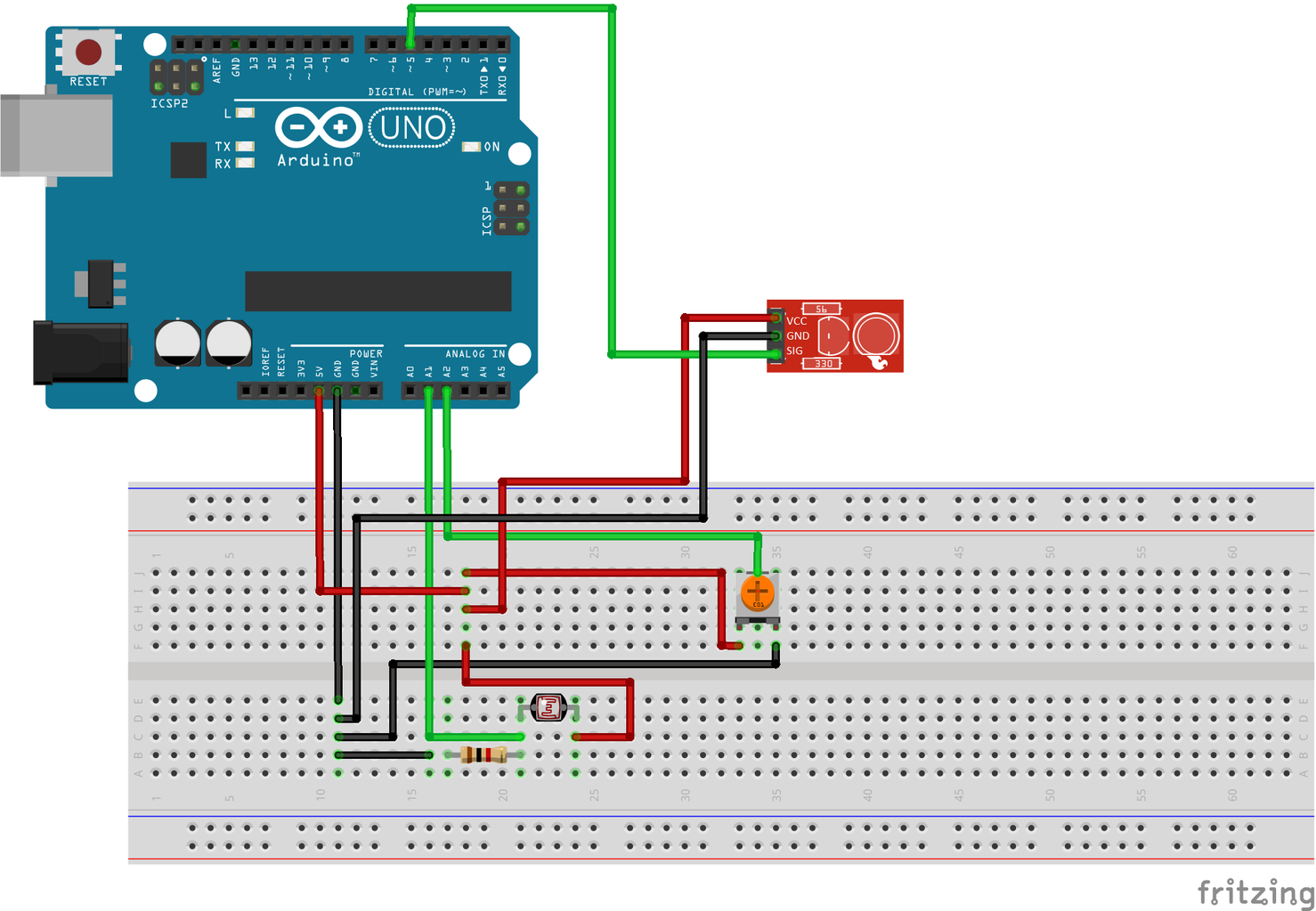
Infrared Sensor
An infrared Sensor has two IR LED’s. One is IR Transmitter and the other one is IR Receiver. IR Transmitter transmits the IR rays. If there is some object in front of it, then the IR Rays are reflected from the object and is received by the IR Receiver. If there is black object or no object in front of it, then no rays will be reflected. As black colour absorbs light, the IR Rays are absorbed by the Black colour. This sensor has a ‘3 pin’ configuration. The VCC and GND pins are supplied with +5V and ground from the microcontroller/ microprocessor. The SIG pin is the signal pin which gives a digital high upon sensing IR rays. The sensor module is equipped with a potentiometer which enables the user to adjust its sensitivity.
Circuit Connections:
- Connect the VCC pin of the Infrared sensor to the 5V line using a connecting wire.
- Connect the GND pin of the Infrared sensor to the GND line using a connecting wire.
- Connect the SIG pin of the Infrared sensor to the Digital pin 5 of the Arduino using a connecting wire.
Step 5: Connect HC-05 to the Arduino

HC-05 Bluetooth Module:
It is a wireless communication module that transmits data serially. Out of the six pins that comes with general break out board, only 4 pins are used. VCC pin of HC-05 is connected to +5V while GND pin is connected to GND of the microcontroller. RX pin refers to receiver and TX pin refers to transmitter. These pins are used for communication between the Bluetooth and the microcontroller.
Note: HC-06 Bluetooth modules can also be used for this project instead of HC-05.
Circuit Connections:
- Place the HC-05 on the Breadboard.
- Connect the VCC pin of the HC-05 to the 5V line using a connecting wire.
- Connect the GND pin of the HC-05 to the GND line using a connecting wire.
- Connect the TX pin of the HC-05 to the Digital pin 10 of the Arduino using a connecting wire.
- Connect the Rx pin of the HC-05 to the Digital pin 11 of the Arduino using a connecting wire.
Step 6: Upload the Arduino Sketch
The system requirement is that only the data of one sensor should be sent to the Android app (which is connected via Bluetooth). Hence, the sensor selection made on the phone and is sent to the Arduino via HC-05.
Before sending data, we need to read, which Sensor has been selected by the user on the app.
Attachments

Step 7: Download the .apk File
Description of the App:
The app has a button that lets the users to connect to an available (already paired) Bluetooth device. It allows also users to select the necessary sensor from the drop-down list, i.e IR Sensor, LDR sensor or Potentiometer. The selected sensor data is read from the Arduino and displayed in the Output Section. It also has a Section where it displays the address of the connected Bluetooth device.
Attachments
Step 8: Download the .aia File (optional)

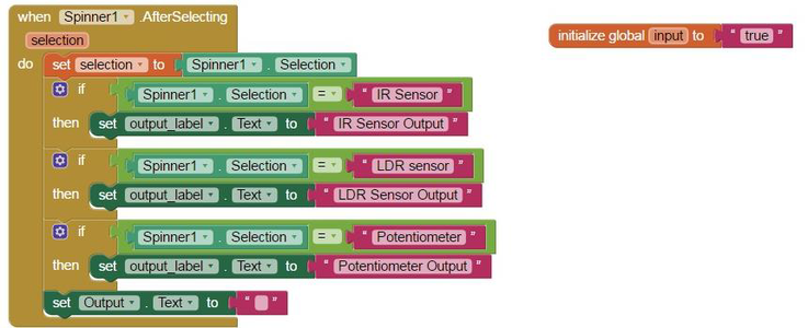

Note: For those who wish to customize the app for their personal projects, you may download the .aia file (MIT App Inventor file) and import it on the MIT App Inventor software. The screenshot of the blocks are given for reference.
Attachments
Step 9: Screenshots of the App


Pair your phone with the HC-05 using the default pass-code :'1234'.


