

Introduction: How to Use the RPLIDAR 360° Laser Scanner With Arduino


I'm a big fan of building sumo robots and I'm always on the look for new interesting sensors and materials to use to build a better, faster, smarter robot. I found out about the RPLIDAR A1 which you can get for $99 at DFROBOT.com . I said I was interested in trying out this sensor and they gave me the chance to try one. After I got the LIDAR I found out I was not allowed to use this type of sensor in the competition I'm planning to attend because it's too expensive.
In this tutorial I'll give you a basic understanding of how this sensor works and how you can use it with an arduino.
Step 1: LIDAR What?
Wikipedia had two different meanings for LIDAR:
- LIght Detection And Ranging
- Laser Imaging Detection And Ranging
In general it can be seen as a distance sensor on a rotating base, which samples range data while continuously rotating. For each successful sample the measured distance is sent with the according angle.
In this case the data is sent over UART.
Step 2: Using an Arduino to Interface With the LIDAR


The LIDAR needs to be connected to the hardware serial port (UART) of the Arduino, for an basic arduino this means you can't send any UART data to the serial console. Because they have only one Serial port. For basic Arduino's with only 1 hardware serial port, you can add an extra software serial port. The library that'll be used in this instructable doesn't support a software serial port (at the moment of writing).
So if you want to be able to send send serial data to the serial console for debugging purposes you'll need an arduino with more than one Serial port. Like there are: Arduino Mega, Arduino M0 / Zero (SAMD21).
If you don't need to send data to the computer to debug you can pick any arduino.
For this instructable I'll be using a more modern and more powerful arduino based on the SAMD21 microcontroller, The Arduino M0 / Zero.
Required parts:
- Arduino M0 ebay link
- Breadboard ebay link
- jumper wires ebay link
- 5V power supply ebay link
- 24 Led ring ebay link
- First you'll need to install the RPLIDAR library from robopeak:
https://github.com/robopeak/rplidar_arduino, this library offers 2 interesting examples on how to use the LIDAR. You can find more information on how to install a library in the arduino IDE in this article: https://www.arduino.cc/en/Guide/Libraries
- Now open the "simple_connect" example code that is included in the library.
- Make the necessary hardware connections from the LIDAR to the arduino:
- Connect the RPLIDAR's serial port (RX/TX/GND) to your Arduino board (Pin 0 and Pin1)- Connect the RPLIDAR's motor ctrl pin to the Arduino board pin 3
- Use an external 5V power supply to power the motor control pin and the LIDAR. - In the void setup you'll have to change following code: "lidar.begin(Serial);" according to the used serial port. When using an Arduino M0 you should change "Serial" to "Serial1". This can be different for other Arduino's.
- The first picture is what the example sketch should look like, lines 60-63 contain the variable names which you can use to get the data from the LIDAR.
- If you want to know what this data looks like you can print this data to the serial monitor, with the code in the second picture.
In the following step we'll make a very basic working project with the LIDAR and a LED ring.
Step 3: Making the LIDAR LED Ring Project


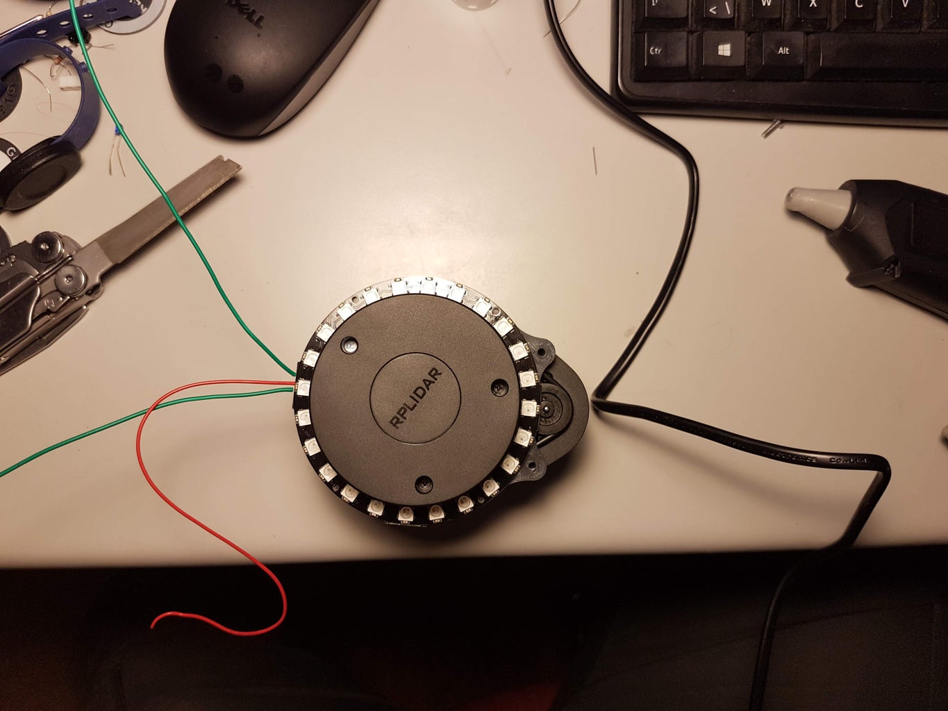


For this project we will mount an addressable led ring onto the LIDAR. This way we can visualize the LIDAR data.
In this specific program the LED will be turned on in the direction of the closest detected signal.
The code for this project is based on one of the examples from robopeak:
https://github.com/robopeak/rplidar_arduino/tree/m...
The changed code for this project is included in the zip file in this step.
Needed parts:
- LED ring: with 24 LEDS big enough to fit over the LIDAR, inner diameter 70mm
- Arduino Zero
- LIDAR
- Separate 5V power supply
- 3D printed part: https://www.thingiverse.com/thing:3185216
- Get all the needed parts
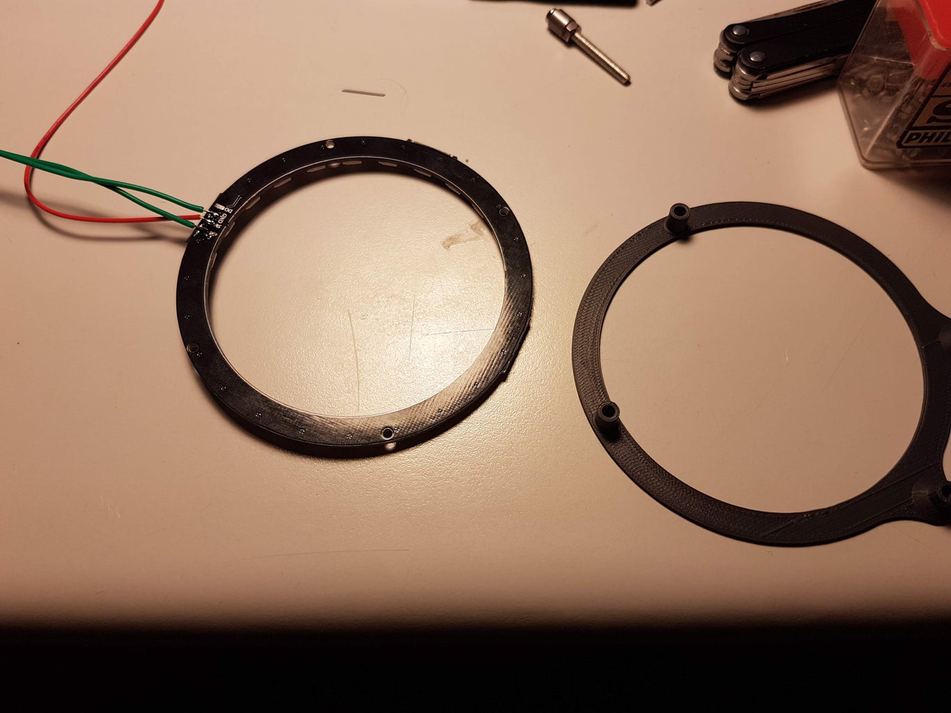
- Solder the wires to the LED ring
- Glue the LED ring to the 3d printed part
- Mount the 3D printed part onto the LIDAR, there are holes in the 3Dprinted part for M2.5 screws but I didn't had them laying around to I just used hot glue
- Connect the wires from the LIDAR to the arduino:
GND -> GND
5V -> 5V of separate power supply
Di -> pin D5 of arduino - Upload the sketch and power up the external power supply
Final result can be viewed here on youtube:
https://www.youtube.com/watch?v=L1iulgiau0E
Attachments


Participated in the
Optics Contest


