Introduction: IPrunes - Aquaponics System


iPrunes - Open Source Aquaponics
Dear Instructablers
iPrunes is my attempt at an indoor aquaponic garden. I wanted to design a fruitful unit that was compact, adaptable and aesthetic. The design for me also had to be easily replicated and re definable as technology advances. The design used open source materials & manufacturing techniques which are widely available in makerspaces globally.
If you like iPrunes then feel free to donate to my design development.
Donate at https://paypal.me/Toppy007
Step 1: IPrunes Video Tour
This is a small video tour of the finished aquaponic system.
Product Overview
I've used perspex/acrylic to create a manifold which allows water to enter and exit 3D printed growing pods. The pods connect to the manifold through a SnapQuik coupling - these are detachable water tight push connectors. The unit is then framed using 20X20 V_Slot extruded aluminium profile. The frame also houses an aquarium where the water pump and filter are submerged. iPrunes uses a 4-channel relay to control the three actuators; a pump, filter and grow light. The relays are wired to a pi via a PCB which can also allow sensors to measure the systems inputs if required.
In the next section we will review the tools and materials required.
Step 2: Parts & Tools (Bill of Materials(BIM) & Tools)


So firstly this might not be the cheapest route to take into aquaponics but I think it is the most stylish!
You should download the bill of materials (BIM) and gather the required essentials! (You can out source your 3D printing & laser cutting or find a makerspace and manufacture them yourself at a considerable saving.)
Also, it's best if you order the V_Slot material cut to size to ensure quality.
The design is also in BETA so I'm hoping that you will tweak the design and develop a better iPrunes to suit!
When it came to tools once you've the components it's really an assembly exercise so minimal hardware is needed.
Tools list as follows (Allen Keys, Screw Drivers, Wire Strippers & Cutters, Multi-tool or Dermal, Router & Trim Bit, Weld-on Applicator, Clamps, Right Angles, Assortment of Zip Ties, and anything you'd think will make the build easier.)
In the next step we will cover the detailed parts and their associated files.
(I'd also recommend you print yourself a bottle opener as this will be quite a lengthy build)
Attachments

Step 3: Parts & Tools (CAD Files & Schematics, STLs)


Presented in this step are the associated CAD files required for 3D Printing.
I'm sorry that I haven't included a walk-through of the CAD assembly design, but I've left to hopefully cross the Atlantic and forgot to create a short movie. But I did remember to upload all the files to GrabCAD
https://grabcad.com/library/iprunes-1
Once again iPrunes is up for redevelopment so please feel free to run with the design.
PLA 3D Parts List;
Foot_V-S;ot_IPrunes_V2.0.STL X 4
Part10^V-Slot Aluminum_Stand_V2.0.STL X 2
Pod_V2.0_XYZ.STL X 10
PowerSocketHolder_V2.0.STL X 1
Tank_RightAngle.STL X 2
HindgeBracketBaseFemale_V2.0.STL X 2
3D_Printed_SpacerManifold.STL X 7
Electonic_BoardSpacer_V2.0.STL X 4
ElectronicsCase_V2.0.STL X 1
HindgeBracketBase_V2.0.STL X 2
SpacerRelay_V2.0.STL X 1
TankPad_V2.0.STL X 4
TopWaterHeadFixture_V2.0.STL X 1
In the next step will will address the laser cutting DXF Files.
Attachments
 HindgeBracketBase_V2.0 (1).STL
- PowerSocketHolder_V2.0.STL
- Pod_V2.0_XYZ.STL
- Part10^V-Slot Aluminum_Stand_V2.0.STL
- TopWaterHeadFixture_V2.0.STL
- 3D_Printed_SpacerManifold.STL
- Electonic_BoardSpacer_V2.0.STL
- TankPad_V2.0.STL
- ElectronicsCase_V2.0.STL
- SpacerRelay_V2.0.STL
- HindgeBracketBaseFemale_V2.0.STL
- Foot_V-S;ot_IPrunes_V2.0.stl


Step 4: Parts & Tools (Laser Fabrication)


I've attached two files required to be laser cut.
You can chose to fabricate the aquarium or just buy one as I found this relatively challenging and more expensive.
I also had issues finding somewhere to cut the silicone sheet gaskets. That said, it cut very well once a makerspace agreed to the material and the cut parameters were found.
You should now be fully equipped to start the Assembly.
Step 5: Assembly (Fixing the Female SnapQuik)


So the first step in the assembly is to insert the female SnapQuik connectors into the acrylic manifold.
Use a bolt to gently rubber mallet them into the front face of the acrylic.
Then trim the back face leaving 1mm protruding. (Acrylic scratches easily so use a spacer and keep the protective film on until final assembly.)
For this step I used a multi-tool with mixed results so I'm open to ideas.
Step 6: Assembly (Fixing Together the Acrylic Manifold)


Now we can start assembling the manifold.
This is very fiddly and it requires some patience. You need to insert some temporary bolts and flip the base manifold so you can layer up the gaskets and internal inserts. Then flip the design once again to place the bolts to finally secure the manifold together.
You should be removing any protective film on the acrylic and then use gloves to avoid fingerprints on the surface.
By the end of this step you should have created the manifold.
Step 7: Assembly (V-Slot Stand Uprights)


In this step we will attach the large vertical V_Slot extrudes.
You'll need to add the manifold spacers and M4 40mm bolts, Attach the bolts, spacers and M4 T Nut Slots loosely then jiggle the V_Slot extrudes into place.
Use a set square to square them to the same length and tighten up.
Step 8: Assembly (UV Gluing Female Snapquik )


You'll have noticed that the female SnapQuik fixings have some play, In this step we will secure them using UV glue.
I recommend using a Bondic Pen. Apply the stiff liquid around the base of each joint and using an ultraviolet light set the glue while applying pressure to the SnapQuik head.
Do each SnapQuik one at a time.
This should now be sealed and have no play, repeat the exercise if they do.
Step 9: Assembly (V-Slot Lateral Support)


We can now attach a lateral V_Slot support.
Using the components pictured attach the aluminium extrude and tighten.
Now put this part of the design to one side because we can start on the base.
Step 10: Assembly (V-Slot Base Building)


Gather the required and remaining V_Slot parts, fasten together the base as pictured making sure everything is squared and level.
Tighten so there is no gaps between the joints.
Hopefully you'll have something that resembles the last picture. If so, let's get onto the next step.
Step 11: Assembly (Feet Attached to Base)


Using the same construction techniques to attach the four feet.
Use the M4 40mm bolts and then tighten and inspect for quality.
Head to the next step after.
Step 12: Assembly (Joining the V-Slot Frame)


Attaching the base to the manifold.
Using the four 90-degree Joining Plates and two Inside Hidden Corners secure the base to the manifold. Once again check for squareness and then tighten to eliminate movement.
The product should be really coming together now! I think you've earned your first beer break.
Stand it up and admire your top effort with a beer.
Step 13: Assembly (Planting Pod Male Snapquik Fixing)


In this part of the project we will finish the interchangeable planting pods.
On each pod do the following;
Drill out the PLA printed planting pods with a 5mm drill bit at both the in and out flows.
Make sure the tubes are clear.
Insert the male SnapQuik fitting with light force and a twisting action.
UV glue both fixings to secure them into place
Test the pod in the manifold.
Repeat the exercise until all the pods are completed.
On to the next step.
Step 14: Assembly (Top PVC Tubing Fixing)


The top fixture allows water to flow into the manifold.
Firstly check that nothing is blocking the waters ability to flow through the part. If so drill the tube profile to clear it.
Add two appropriate sized O-Rings to the 3D printed part and lightly insert it into the top section of the design.
Have the two rubber O-Rings fit into the middle of the two 5mm sheets of acrylic.
Once sitting securely move onto the next step.
Step 15: Assembly (Attaching Tank Pads)


Add the four tank pads.
Use the M4 20mm bolts and secure using the same techniques as used for attaching the feet.
Lets crack on to the next step.
Step 16: Assembly (Light Bar Attachment)


In this part of the design we will attach the light used to aid the luminescence required for plant growth. Once again another fiddly bit of assembly.
Using the 2 X 3 printed parts initially attach the hinging system loosely.
Please be aware that the two fixing points to attach the the system to the V_Slot contain a design flaw where as the two fastening bolts are located too close together and its difficult to rotate them to fasten!
Redesign coming ("A man can only admit when he was wrong and ask for forgiveness")!
Now you can attach the light bracket hinges to the 3D Printed parts. Attach the adjacent brackets loosely as well.
Now attach the light to its bracket and fiddle with the placement as required.
Tighten the bolts now and adjust the fitting so the light hangs as close to square as possible.
There will be some sag in the light but I still think its an adequate solution ready for your own redesign.
If you've got this far your once again your ready for another beer.
Step 17: Assembly (Fish Tank Weld-On Glue Up)


Now, lets make our tank.
Using a range of clamps and squares arrange the acrylic parts to form the aquarium
Add tape to secure the sides together with a small overlap on edges (we can trim these later).
You can now use your weld-on cement to glue the tanks edges.
Using a bottle applicator go through each edge using the water thin cement sparingly, I tilted the edges to avoid run off onto the surface that will remain.
Hopefully you'll see the edges change transparency as the glue is being applied.
After leave the tank to cure for 48 hours.
It's difficult to get a sealed professional finish and I do recommend buying a tank if you're not confident.
Step 18: Assembly (Routing Acrylic Fish Tank Edges)


Lets trim the excess overlap acrylic.
Using a router and a trim bit go along each edge to achene a flush finish to the tank.
After you'll notice the edges really start to glow now.
Now lets see if it holds water!!
Step 19: Assembly (Gluing Gaps in the Tank)


I got lucky!!!
When I filled the tank I couldn't fine any leaks. wow! But if you do find some there is a fix. It comes in a thinker form of Weld-on 16 which you can apply along the joint of any area you find is leaking.
Once again leave for the necessary curing time.
Test again and if all's good that's the hardest bit of the build tackled.
Time for another beer break.
We're moving onto the control system assembly.
Step 20: Control System (Pi & 4 Channel Relay)


In this section of the build we will start developing the electronic control system which will allow us to control the actuators iPrunes uses.
This may look complicated but it is relatively simple. We have a Raspberry Pi Zero W controlling a 4-Channel Relay.
The PCB I had started to design will allow you to eventually monitor the system but sadly I ran out of money and time to continue this aspect of the design.
(The PCB I have designed is optional)
The first thing to do is to set the Pi up so you can connect to it in a headless mode; either a SSH or VNC connection! I Prefer a VNC connection which allows you a desktop view of your Pi as I'm no pro when it comes to command-line syntax.
Next connect your Pi to the 4-Channel Relay using 6 DuPont Wires Female to Female forming the following connections.
Pi Zero W 4_Channel_Relay
GND ============= GND
GPIO27 ========== Channel_1
GPIO22 ========== Channel_2
GPIO06 ========== Channel_3
GPIO05 ========== Channel_4
5V ============== 5V
You can view the EasyEDA files to get a greater understanding of the electrical hardware schematic.
Please remember to follow me if you do!
Editable EasyEDA File
https://easyeda.com/editor#id=|cac35235b3b148699bf...
Schematic Design
https://easyeda.com/christophertoplisek/iprunes-co...
PCB Design
https://easyeda.com/christophertoplisek/iprunes-co...
By the end of this step you should have the Pi with or without the PCB connected to the 4 Channel Relay and ready to run code through a SSH or VNC Connection.
You can also attach the electrical components to the 3D Printed board and use the nylon bolts to secure them down. Remember to use some spacers where required.
Step 21: Control System (Power Supply Unit)


This section of the project is all about dividing the mains power through the relays and actuators!
Proceed with Caution (Mains 240 Voltage)
Please ensure you are a competent electrician before attempting this step.
Better safe then sorry!
The first step in this section is to solder the IEC 320 C14 Male 3P to its Neutral(BLUE), Live(RED) and Earth(GREEN/YELLOW) wires.
Then use your 380V 400V 30A Dual Row 12-Terminal Electric Strip Blocks to divide the power!
Cut down one block to a 5-block Strip to Divide the Live(RED) voltage as show in the picture.
Use another and divide the Neutral(BLUE) & Earth(GREEN/YELLOW) creating four mains terminals.
You can now zip tie the terminals to the board and wire the remaining supplies together.
Lastly complete the connections into each individual relay and then to each corresponding terminal.
I can supply more details if you can't understand whats happening!
You can use a multi-meter to test the power connection through each junction!
I also tinned each wire to aid connecting the device up!
Do not plug the mains power into a socket terminal until we do some further testing which is presented in the next step.
Step 22: Control System (Uploading Python Script & Testing)


Under NO Circumstance Plug Mains Power Supply In!
We can test that our electrical components are wired correctly before we turn the mains on!
We will test the relay connections to the Pi first
Firstly connect the the Pi to an adequate USB power supply!
Run the script called Test.py from the command-line!
You should see the lights on the relay change in a sequence. You should also hear a click.
If all four relays light up one after the other you should have everything wired correctly to the relays from the Pi.
You can also test the LIVE wiring through the relays by using a multi-meter
Continuity testing is the act of testing the resistance between two points. If there is very low resistance (less than a few Ωs), the two points are connected electrically, and a tone is emitted.
Place the two probes on each side of the relay and wait for it to be triggered. Once the light indicates it's on you should hear a tone from the multi-meter.
If you do not get a tone it's wired incorrectly!!! Test the other connections in the channel and the other connection on the relay!
Still some more wiring to do but you're now on the home strait! You can now attach the board to iPrunes using spacers, then onward to the next step.

Step 23: Control System (Connecting the Actuators)


In this step we will connect the actuators! (Water Pump, Filter, Grow Light)
Once Again Make Sure NO MAINs POWER Is Connected!
Connect each individual actuator to one of the 4 terminals created by the strip block terminal.
Remember to keep any transformers the actuators have and wire them in after you've connected it to the mains terminal!
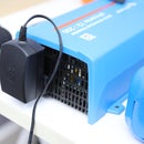
In my project the LED Grow Light bar contains a transformer which can be seen connected after the mains terminal and attached to the bottom of the electrical component board! (The Big Rectangle Metal Box)
Remember to leave enough wire length for the actuators to reach where it'll be placed on the unit!
Tidy the remaining cables into the V_Slot extrudes and secure with zip ties.
Once you have striped and wired all the actuators your ready to proceed to the final testing process!
Go forth to the next step!
Step 24: Testing (Acrylic Tank, PVC & Actuators)


Now we will run our Python script and test the actuators.
Go into the command line on the Pi and once again run the Test.py file.
Now plug an ICE cable into the ICE port on iPrunes and then into a mains power socket.
DO NOT TOUCH The Electrical Board While Plugged In!
As the Pi activates the individual relays you should hear each Actuator turn on in sequence!
Make a note of the sequence and try to figure out which terminal is activated by which GPIO pin! The best way to do this is to restart the program and make a note of each actuator as it runs through them!
For example;
GPIO27 = Light
GPIO22 = Filter
GPIO06 = Pump
GPIO05 = N/A
You can now cut and fit the PVC to the water pump! Zip Tie it to the V_Slot to secure it, fill your tank with water and once again run the Test.py script to see if the water can be pumped to the manifold opening!
Step 25: Testing (Water Supply to Pods)


Were almost done!
Place all the pods into the manifold and check that the water is flowing in and out of the pods. I've design the pods so they hold an amount of water but will drain to a level as the pressure increases on the pods volume.
Leaks! Its important that you don't have any leaks escaping the system! This could damage the electrics and create a risk of electrification!
If all's good onto the next step.
Step 26: Testing (Add Planting Capsule & Set Python Script Timings & Cron Job)


At this point add your mesh planting pots, I had to cut them down the side to get a tight fit on the internal lip of the pods. (Pods might need a redesign!)
The final scripting exercise.
What we need to do is set the timings on the actuators so they will automatically control our system!
The LED Grow Light should come on between 08:00 and 22:00.
The Filter should be activated when the Pump is not in use.
The Pump needs 50 secs to refill the pods every 300 secs.
To do this we can create a program similar to the Test,py. Download the attachment called iPrunes_RelayCode_V2,0.py. You can read the annotated script to better understand it!
Once you understand it, upload it to the Pi and execute the program.
Remember you can set your own timings for however you want to control your system.
Once your happy with the way your control system is scheduled you can add it to the Cron Jobs file.
This will allow the program to run on restart automatically! Use the link below to understand this better! No point me repeating what's been written better elsewhere!
https://www.ostechnix.com/a-beginners-guide-to-cro...
You're done and congratulations for getting yourself this far.
Please proceed to the last step.
Attachments
Step 27: Finish Line


Thank you so much for taking the time to read this Instructable.
I can't wait to see what you'll grow and I'd really like someone to develop the design further and welcome your ideas.
My plan is to eventually design a machine learning algorithm to control and optimise the growing parameters of iPrunes. So follow me for when I eventually apply the sensors and train the machine learning algorithm.
As mentioned previously I'm currently hoping to boat-hike as a crew member on a sailing boat crossing the Atlantic so if anybody knows anyone setting off from Las Palmas please let me know!
I'd also appreciate anyone who'd fancy buying me a beer by donating to the PayPal link posted below
https://paypal.me/Toppy007
Happy building everyone.

Participated in the
Make it Glow Contest 2018