

Introduction: Integration Platform Ubidots With LOGO! Siemens Using Node-RED


apFor some weeks I have done some tests with a LOGO! (logical module) from Siemens, for a few months I have seen that they use it in basic industrial applications, although I do not personally consider it 100% a PLC, it is easily integrated into monitoring and control applications for simple processes.
![]()
Step 1: LOGO! by Siemens
You could say that this equipment is the cheapest or affordable "PLC" that Siemens has in my country has a cost of approximately 200 USD, for the simple reason that being a Siemens brand is synonymous with confidence and perfect robustness for Domotica applications.
Since the following tutorial is a little more extensive it has been divided into 5 parts that we will see next.
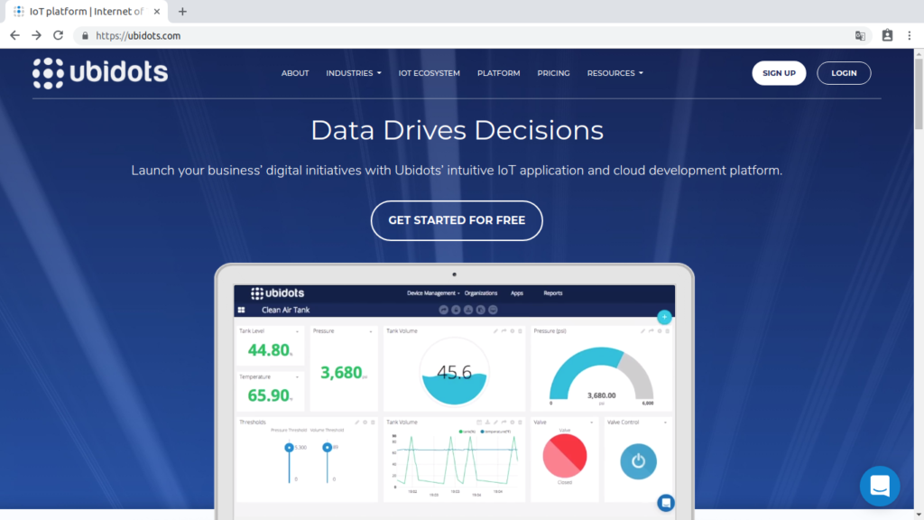
Step 2: 1. IoT Platform Ubidots
Our account on the Ubidotsplatform.
Next we will perform the final test of this team performing the integration with theIoT Industrial Ubidots platform, before starting I recommend other tests and interesting integrations with Ubidots.
Recommended: PDAControl / Ubidots
Website: Ubidots.com
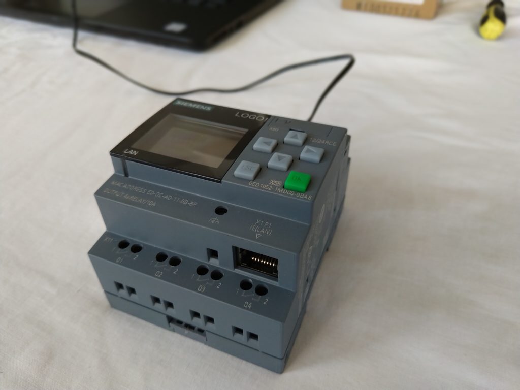
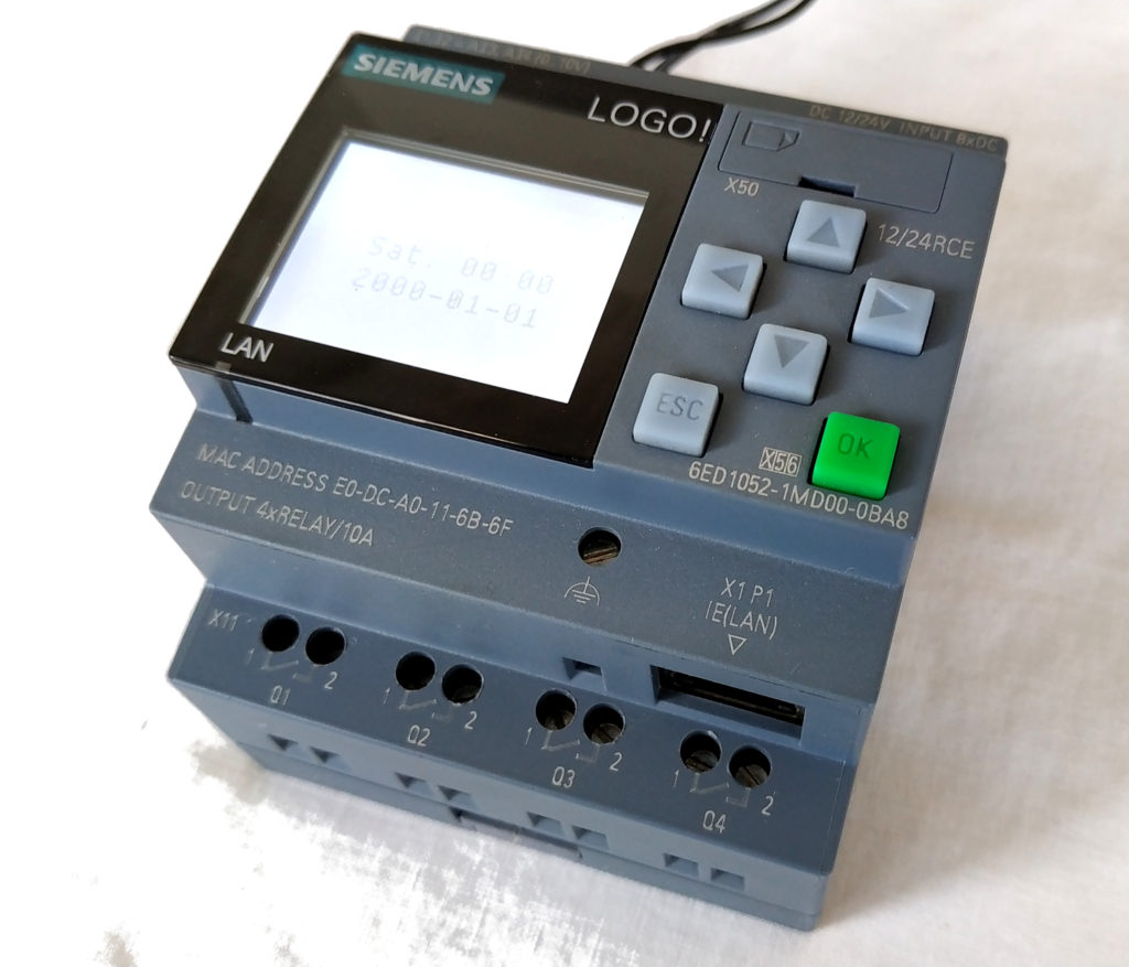
Step 3: 2. Review LOGO! 12/24 RCE Reference 6ED1052-1MD00-0BA8
This version LOGO! 12/24 RCE 6ED1052-1MD00-0BA8 has interesting features, mainly Ethernet communication which expands the possibilities of integrations, a robust and reliable hardware.
Recommended Tutorial: features and documentation features
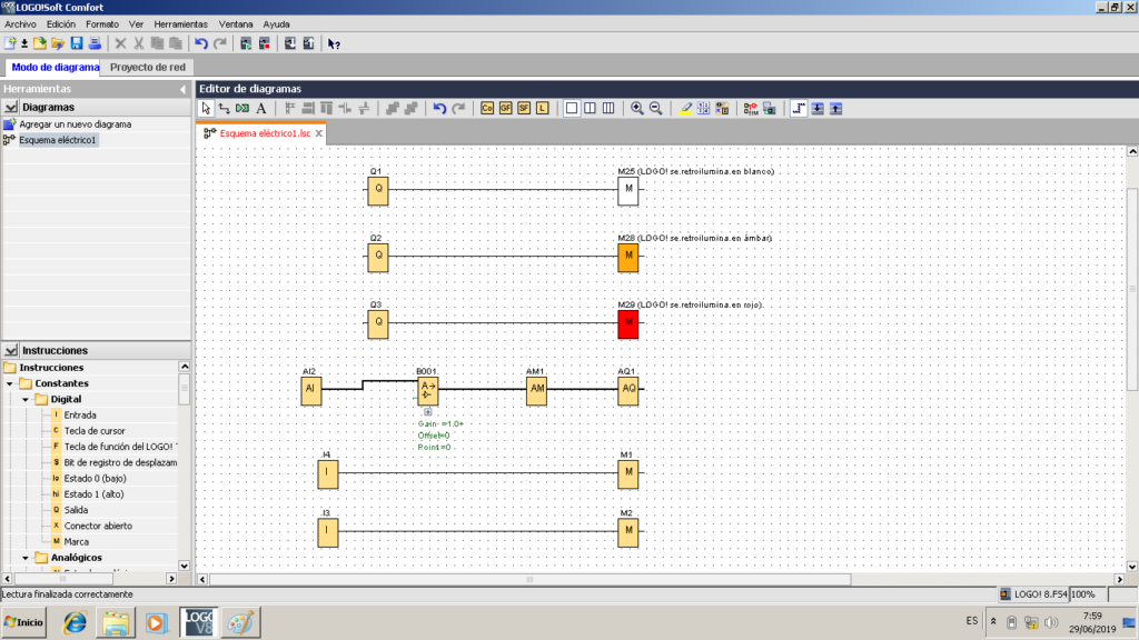
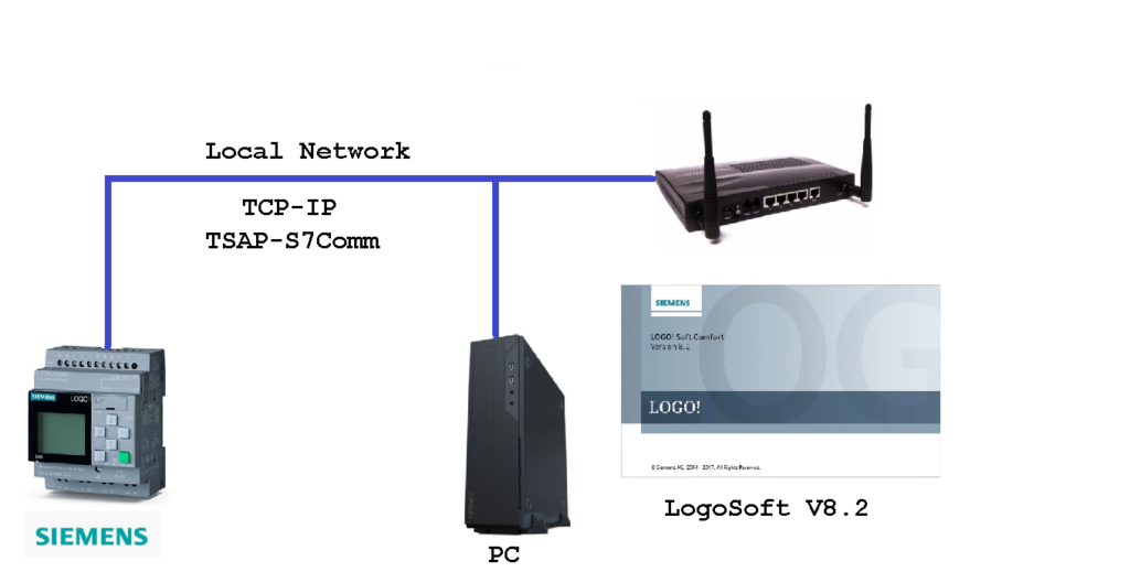
Step 4: 3.Configuration and Programming LOGO! With LogoSoft
These equipments have programming software "LOGOSoft", it is programmed by means of logical blocks or Function Block Diagram or FBD, previously we have created an example, each output will realize the change of color in the LCD screen and analog input reading.
Download this LogoSoft example at the end of the article.
Proposed architecture for programming and configuration.
Recommended Tutorial: Download of LogoSoft Demo version.
Recommendation: watch the full video of this test to understand how it works: Integration Industrial LOGO! Siemens with Ubidots Platform IoT.
Node-RED in Raspberry Pi 3
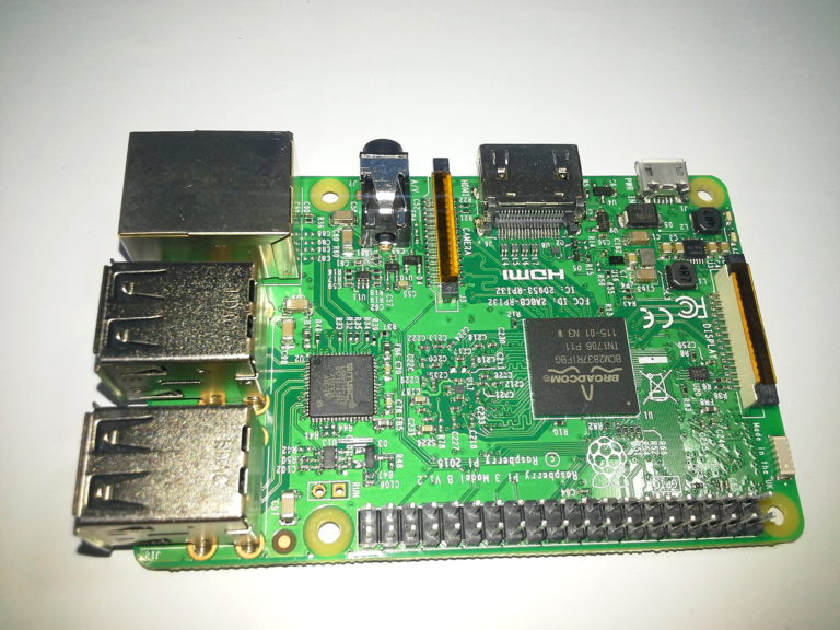
To perform the integration between the LOGO! and the Ubidots platform we will use a Raspberry Pi 3 model B in which we have previously installed Node-RED.
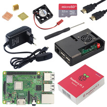
Buy it here: Raspberry Pi 3 Model B or B+ with Case
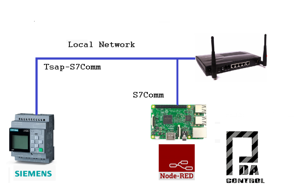
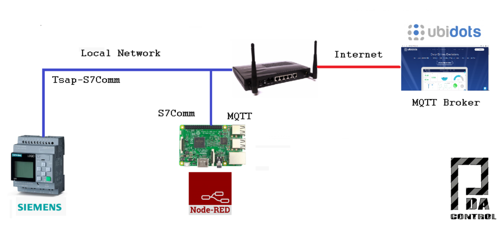
Step 5: 4. Communication LOGO! and Node-RED Through S7Comm
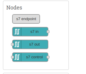
The LOGO! Modules they use the S7Comm protocol for communication with remote applications, thanks to the Node-RED developer community, they have created S7 nodes for ethernet communication using TSAP.
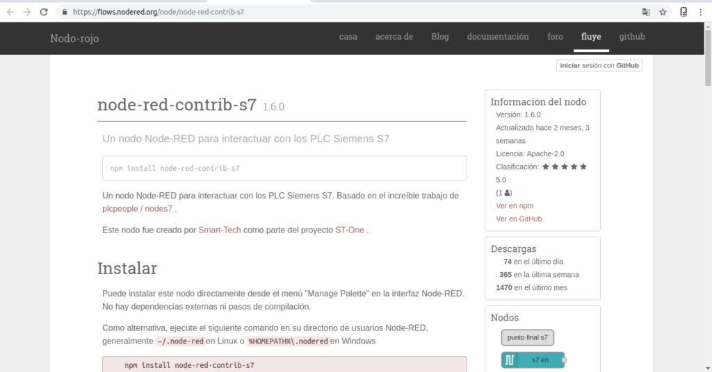
More information Nodes: node-red-contrib-s7
Proposed architecture: LOGO! Integration and Node-RED.
Recommended Tutorial: LOGO integration! and Node-RED through S7Comm.
Step 6: 5. Connection Node-RED and Ubidots
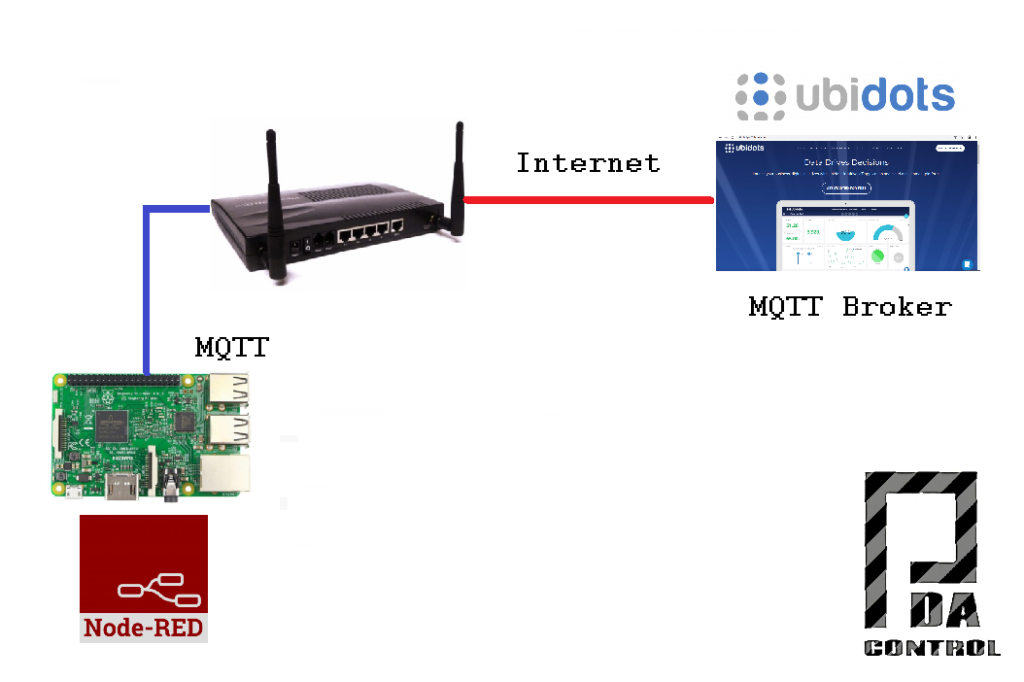
The communication between Node RED and Ubidots is done using the MQTT protocol, making the connection to the Ubidots Broker, there are 2 methods to make the subscriptions and MQTT publications.
Recommendation: watch the full video of this test to understand how it works: Integration Industrial LOGO! Siemens with Ubidots Platform IoT.
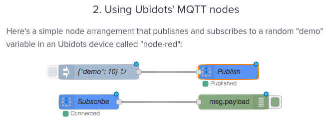
- MQTT nodes of Ubidots: facilitate or simplify the configuration.
 information from https://help.ubidots.com/articles/1440402-connect-node-red-with-ubidots
- Basic Node-RED's own MQTT nodes: They require more dexterity for the configuration.
 information from https://help.ubidots.com/articles/1440402-connect-node-red-with-ubidots
Architecture proposed connection Node-RED and Platform Ubidots
Complete Documentation :Connections Ubidots and Node RED
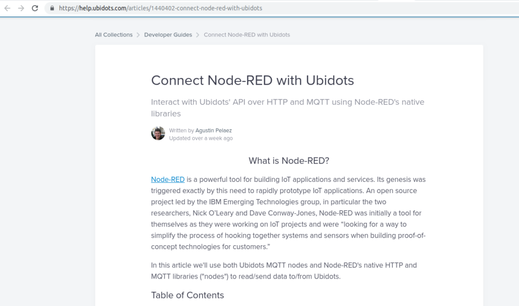 https://help.ubidots.com/articles/1440402-connect-node-red-with-ubidots
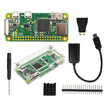
Buy it here: Raspberry Pi Zero Wireless 1GHz 512Ram
Step 7: Final Video: Integration Industrial LOGO! Siemens With Ubidots Platform
To facilitate the understanding and scope of the application I recommend to complement with the following video, to enable the subtitles, in this video I will explain in more detail the application as a whole.
Step 8: Tests
From Ubidots we will carry out the control and supervision LOGO! through Node-RED.
Architecture Implemented for this test.
LOGO! Connections
The following connections have been made:
- 3-position electric selector to activate 2 outputs at 24VDC
- Potentiometer 10k to simulate analog input of 0-10VDC
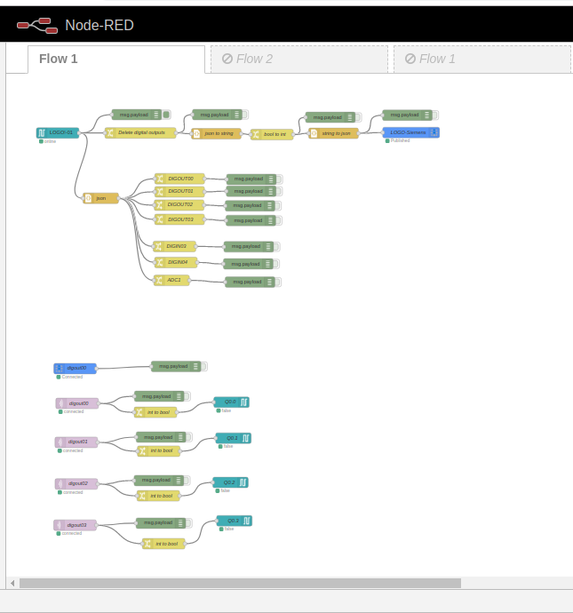
Implementation in Node-RED
Bidirectional communication between LOGO! and Ubidots below, we will see some required configurations in Node-RED, Download the node-red import example at the end of the article.
Recommendation: watch the full video of this test to understand how it works: Integration Industrial LOGO! Siemens with Ubidots Platform IoT.
- Complete view nodes
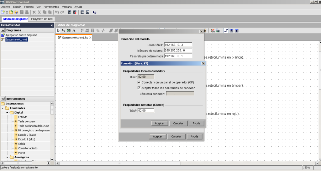
Configuration LOGO! TSAP communication via S7Comm.
Configuration TSAP LOGO! in LogoSoft.
List of Variables of the LOGO!
- 4 digital outputs to Rele (Q0, Q1, Q2, Q3).
- 2 digital inputs (I3, I4).
- 1 Analog input (I8 = DB1 INT1118) 0-1000 points, 0-10VDC.
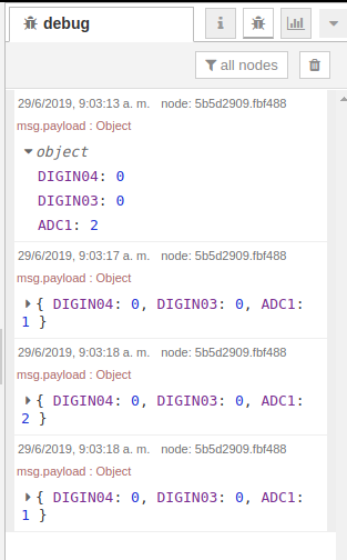
Log reading and filtering from LOGO! and sent to Ubidots, using a JSON Object.
All records read (JSON Object).
We eliminate the digital outputs for the sending to Ubidots of only digital inputs / analog inputs.
Reading from Ubidots and writing in the 4 Digital outputs (Relay) LOGO! , we will use the basic MQTT node.
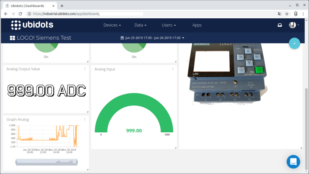
Step 9: Dashboard Ubidots
Panel Control from Ubidots.
- Top Control of 4 Outputs.
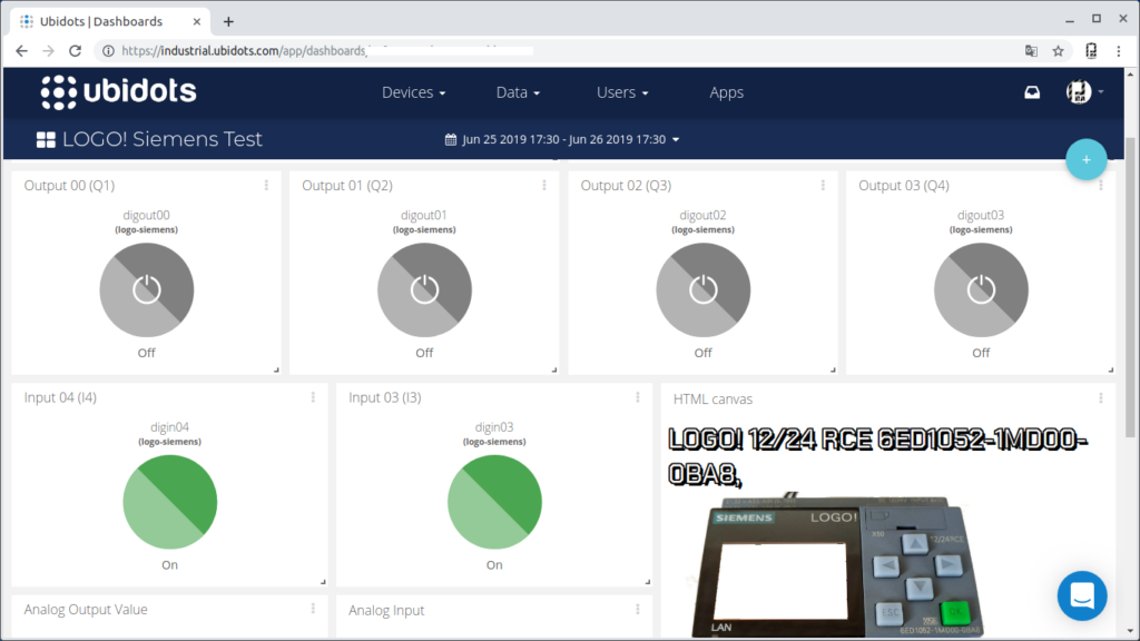
- Central part detection of change of 2 inputs digital inputs and designLOGO! in "Canvas" html, javascript.
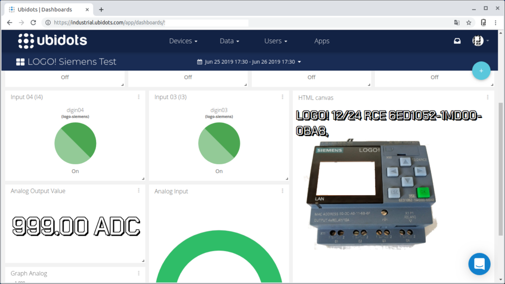
- Bottom collection of analog input value.
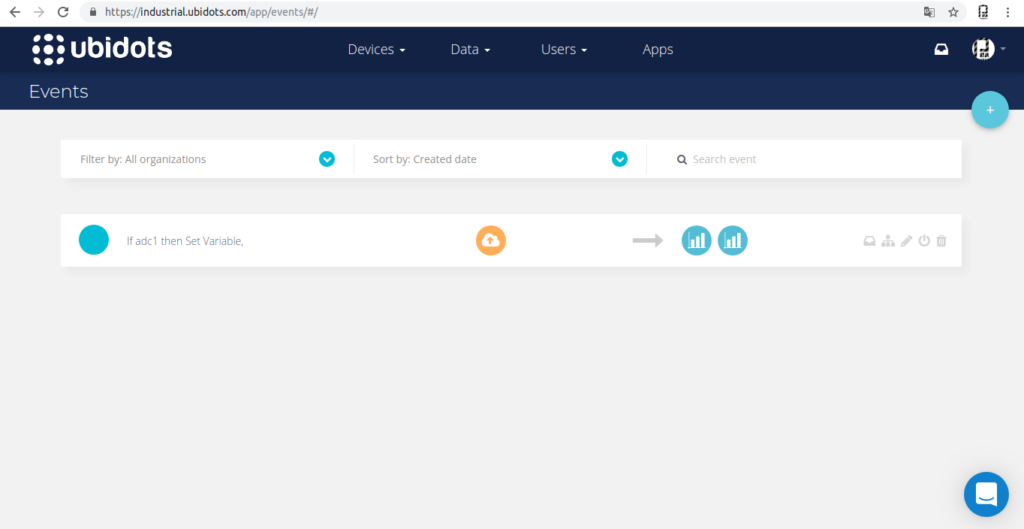
Step 10: Control With Events in Ubidots
Ubidots allows you to configure events triggered by conditional, in this case the following condition has been created:
- If ADC> 500 for more than 1 minute = activate (digital output 02) color Red LCD.
- Active Event
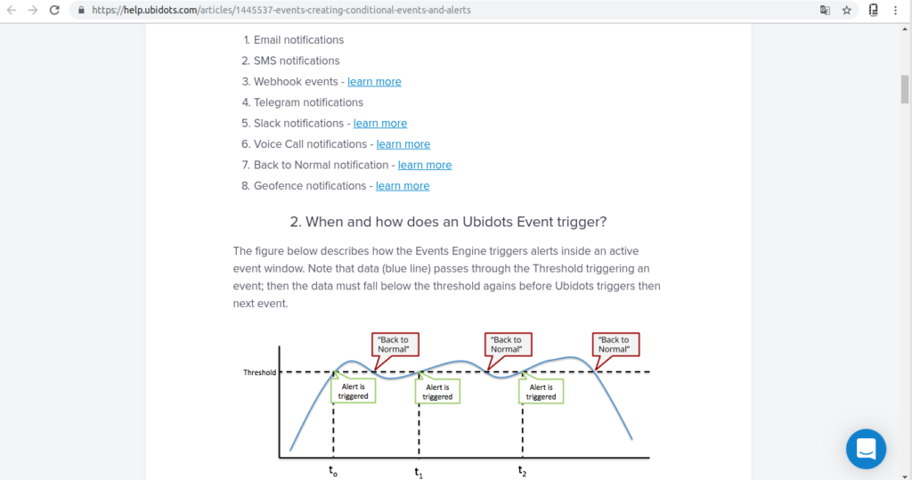
More information: Events an alerts in Ubidots
Step 11: Recommendations
Mainly I recommend starting watching the previous tutorials on LOGO! these specify specific steps concerning configurations.
The S7Comm nodes are those that allow integration, although we have not explored their scope in more complex applications, I recommend discretion in very complex implementations, then I will propose some possibilities.
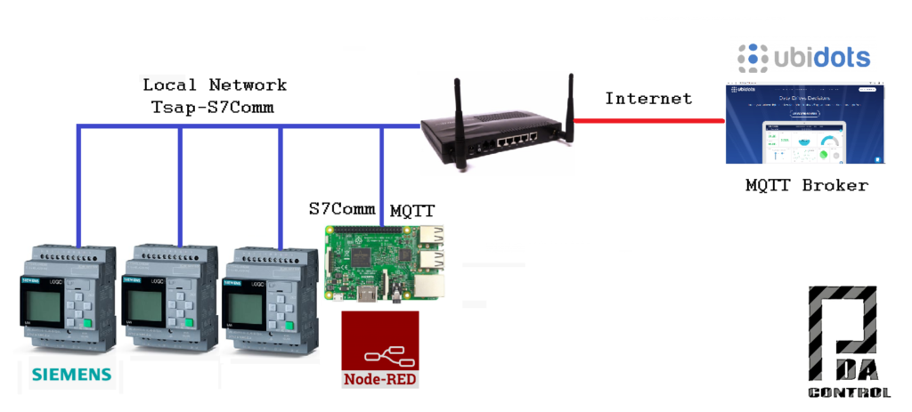
Case 1: I consider that several devices to a single Raspberry Pi, would not be practical given the RAM capacity and processing, in the case of the Raspberry Pi 3, I hope to perform future tests with the New Raspberry Pi 4.
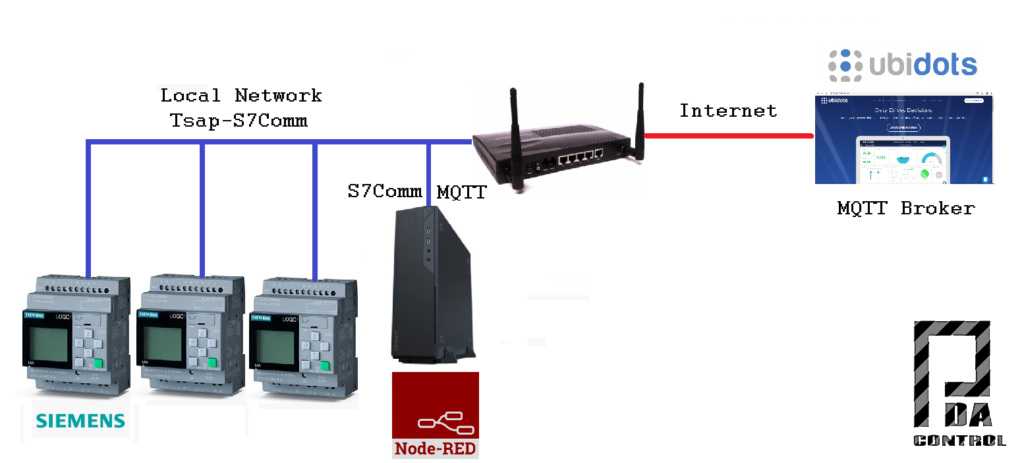
Case 2: This architecture is more robust since it has a server or PC with better processor and more RAM memory, possibly allowing to manage more devices.
Warning: we have not performed any of the tests proposed in the previous cases so we do not know the scope and functionality of the S7Comm nodes with multiple LOGO! Devices, we only analyze and assume the possibilities.
Step 12: Conclusions
In this case the control and monitoring was carried out, and the Ubidots events module was used, which has many features.
This is a basic test, you must take into account more factors before implementing it in real applications, safe conditions referring to the activation of outputs.
The LOGO! I consider them perfect for home automation applications and basic automation or non-complex processes and they are very cheap.
This test was made to open possibilities between industrial hardware and IoT platforms in this case Ubidots, which has a lot of benefits.
Recommendation: watch the full video of this test to understand how it works: Integration Industrial LOGO! Siemens with Ubidots Platform IoT.
Thanks to Ubidots !!!
Thanks to Smart-Tech as part of the ST-One project, the creators of the S7Comm Nodes for Node RED.


