

Introduction: WiFi Enabled Arduino - Interfacing With Web APIs


Are you familiar with Arduino, but are looking for a little more connectivity in your projects? This Instructable goes over a new (and cheap) wireless module that has hit the embedded world hard - the ESP8266. This little module is a perfect way to hook your Arduino project into your WiFi. What you do with it is entirely up to your imagination. This project demonstrates how to tie into the WeatherUnderground API and get weather data for your area (or anywhere in the world you choose).
Things you'll need for this Instructable:
- Arduino or other microcontroller and a working knowledge of it (UNO clone for $12.19USD or MEGA for $22.94USD)
- An ESP8266 module (Here for $2.42USD)
- Breadboard
- Jumper wires
- Home WiFi
- Wunderground API key (available free here for non-commercial use)
Things you SHOULD have:
- An independent 3.3V power supply (for the ESP8266)
- A 5V to 3.3V logic level shifter
Step 1: Step 1: the ESP8266


This tiny module is the ESP8266. It provides a lot more functionality than just WiFi; it is a full SoC capable of executing code. For the purpose of this Instructable we will be using it purely for its WiFi capabilities though.
The ESP8266 uses a 3.3V power supply. Some people have supposedly run it on 5V, but don't risk it. This means that to "properly" use it with an Arduino you'll need to use a logic level shifter. I have been using it without one for the past couple months without any ill effects, but this doesn't mean that the device couldn't potentially suffer damage at some point. Also, active transmission current can be quite high. I suggest powering this off an external power supply rather than USB. Sometimes the current will spike and the device will fail to power completely, data will come across corrupted, or other unexpected side-effects will occur.
Another thing to note with this device is the CH_PD pin. This pin needs to be driven high for the device to power up. I overlooked this for a long time and it caused numerous headaches.
If you aren't too familiar with the embedded world yet, you should read up a bit on AT commands. These are what facilitate our ability to talk to the ESP8266. Once you have your module you should probably test it with a USB to TTL converter to figure out how everything works, or you can just wait and try running code on your Arduino. A full list of the commands for this module are available here. I found this site very helpful in learning about this module.
Once you get more experienced with the use of this module you can actually upload code to it to control the GPIO pins onboard. This is beyond the scope of this project, but it doesn't mean you can't develop something totally cool all on your own with it.
Important:
Not all the ESP8266s are made equal. Make sure you check the baud of yours. Mine was 115200 baud, but other users report different rates.
Step 2: Step 2: the Arduino
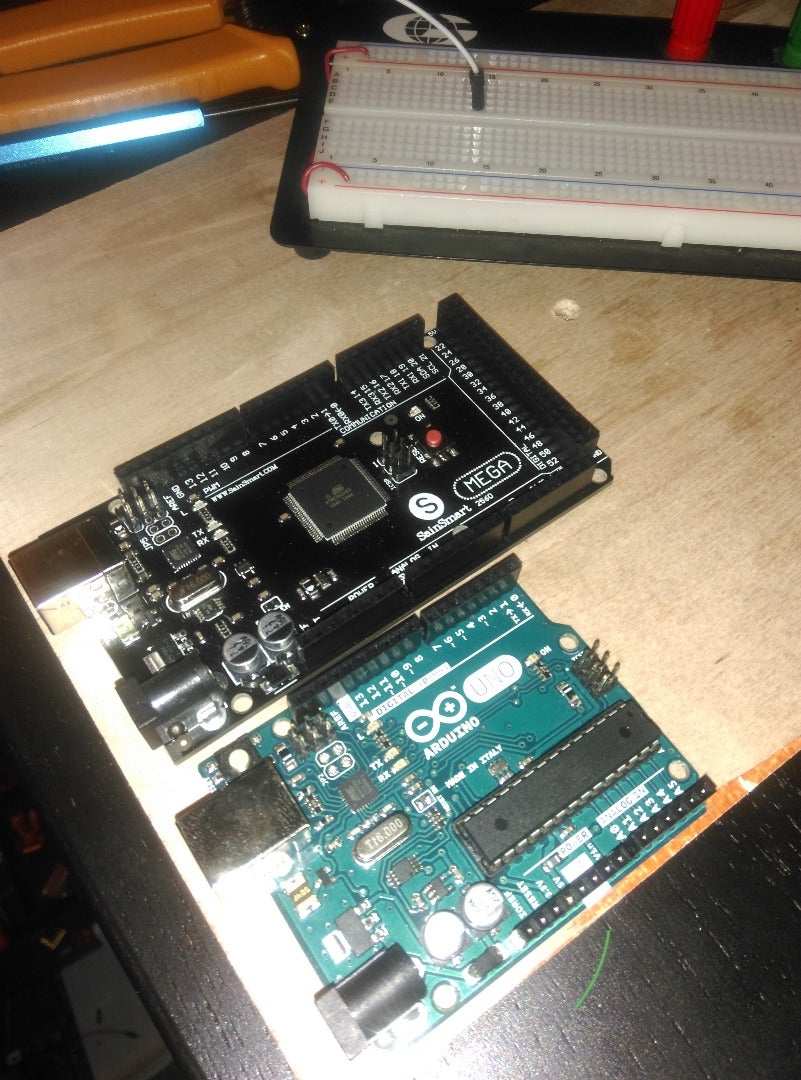
This should be a familiar device to most of you. This is the Arduino. It is an excellent tool for introduction to the embedded world. The Uno will probably be the most familiar sight. It is powered by the Atmel made ATMega328 MCU. The one shown above is the Arduino Mega which uses the ATMega2560. I HIGHLY recommend the Mega as it provides some extra serial ports so you can connect to a program like Putty and several other serial devices at the same time. I used the Mega for testing purposes, then ran the final product on an Uno using I2C to connect to an FPGA
If you've never used an Arduino before now, play with it a bit. A working knowledge of the Arduino will help you immensely when adapting this project to your uses.
If you have a different microcontroller that you like more (TI Launchpad or PIC32 for example) the same principles will apply to using them.
Step 3: Step 3: the Wunderground API

This is the real power behind our project. Weather Underground is an awesome site that provides an API to local weather data for projects just like this! Make sure that you don't go over their limit for API calls though, you might get billed. I chose this API for two major reasons:
1. It is super easy to use. In no time at all you'll be grabbing the weather and displaying it in cool LED powered ways.
2. It has an AUTOIP function. The API will automatically get your location based off your public IP, so as long as you aren't routing through a proxy you won't have to change the API calls at all.
This API provides a wealth of information that you can use for your project. It gives you city name, lat/long coordinates, epoch time, time zone, and all the weather information you could ever hope for. My project focuses on the current weather and temperature, but I'm sure you all can come up with creative ways to use all the information.
When you sign up for Wunderground you'll be given a unique key. This is what allows you to access the data that Weather Underground provides. Once you have your key you'll need to know how to see the data. A call to this API is a simple HTTP GET request, so you can just type a URL into your browser and see what you get!
Let's look at the API call.
http://api.wunderground.com/api/ key here>/conditions/q/autoip.json Make sure you replace with your actual key!!!
This is the basic call for data. Put your key into the URL and fire away. The API will return a .json file with information regarding the weather in your area. Mine is the wunderground.txt at the bottom of this step. Look through it real quick. See how much data they provide? Tons. You can customize the string to get different data too. Forecasts, history, change the location. It's all really up to you. This simple call is really all that we need for this project, so let's move on to the Arduino code.
One neat idea to consider - Attach a Bluetooth module to your IoT-duino and write a little Android/IOS app that lets you change the location in the API get string. Now you can see the weather anywhere in the world!
Attachments

Step 4: Step 4: the Code
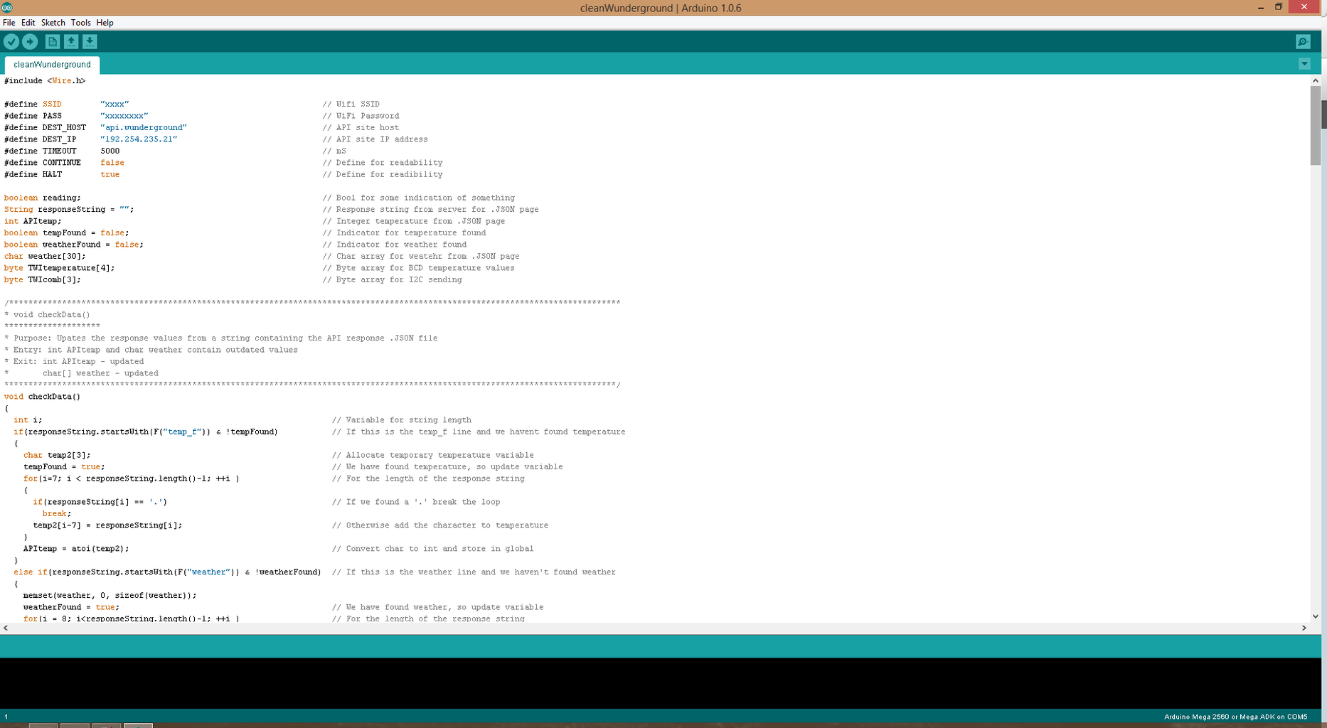


So I'm sure at this point most of you are familiar with the Arduino IDE. We will be using that to upload our weather getter code to the Arduino. I've attached a cleaned and documented version of the code to this step, but we'll go over it a bit here (not laboriously, just enough so you understand what's going on).
The first part of the code is our #defines, just to make life a little easier. We also have a few variable at the top that help us parse out the data a little easier.
setup() Function
Here we go, this is how we connect our ESP to our Arduino. I reserved some space at the top for the string response. This is a hold-over from a previous iteration of code that had repeated stack crashes because the .JSON just overwhelmed my little micro. You can probably throw this line of code out, I kept it. After that you see I start up an I2C (TWI, Wire, SMB, whatever...) connection. This is where my data is actually going. Next comes the Serial. This is the connection to the ESP, notice the 115200 baud. That's SUPER important to get right, otherwise your Arduino is speaking English and the ESP is speaking Cantonese and everyone is confused. You'll notice the AT commands are back, I told you they'd be important! First our code checks to make sure the device is ready by performing a software reset and waiting for the ESP to respond. After that we set the ESP to station mode and allow multiple connections. We can connect to multiple APs, but for our use now we only will be using one of the connections. Following that is an attempt to connect to the WiFi (next function we look at). Once we've successfully (hopefully) connected to the WiFi we push on and connect to our host (in this case Wunderground).
connectWiFi() Function
This function is the meat and potatoes of our code. So what we have here is a command (AT+CWJAP) that is telling our ESP to join an access point. It is followed by the AP SSID and password. If the ESP returns "OK" then we've successfully joined the AP. If not, the connection failed. If you're using a MEGA or other multi-serial microcontroller you can set it up to send the PC messages of what's going on. I'm sending my data over I2C to an FPGA, so I just threw away the responses.
loop() Function
This is the last major portion of the code. This area connects to the Weather Underground API and downloads the data. Once the ESP starts to send data back we push it into the response string variable we declared earlier. I captured the data line by line (starting with " and ending with ,) and looked for the data I needed (temp_f and weather). This keeps the amount of data the Arduino is trying to store/parse at one time down to a minimum.
Other Functions
Most of this code is pretty well documented, so you should be able to figure out what is going on in the rest of it. I go through and look for temp_f and weather. I then convert those values into bytes to send to my FPGA (keeping the size minimal). I converted the weather into a 1 byte value. This gives me up to 256 different weather codes. I then used a simple method to convert the temperature into Binary Coded Decimal and send that to the FPGA in 2 1-byte packets (4 digits total on a seven segment display).
Credits
This code came partially from my own work and partially from that of others. I don't remember all the sources that I gleaned ideas and code from, but if any of you happen upon other work that looks like this, let me know. I'd love to give the credit where it is due.
Attachments
Step 5: Step 5: the Circuit


This part is fairly simple. If you're like me and not super concerned about the logic level shifter, just connect the two together. Make sure you connect the RX of the ESP into the TX of the Arduino and the TX of the ESP into the RX of the Arduino. If you don't the ESP and the Arduino will both be yelling at each other but nobody will be listening. Connect your VCC pin to 3.3V and your GND to, well, ground. The only sneaky pin here is the CH_PD pin. This is the Chip Powerdown pin. When this pin is low it tells the ESP8266 to power itself down. If you want close control of the ESP tie this into one of your GPIO pins on the Arduino, otherwise just connect it to 3.3V so the ESP is always on. For even more control tie the RST pin on the ESP into the Arduino too. This way, if need be, you can perform a full hardware reset on the ESP.
---------Connections---------
--Arduino---|---ESP8266---
TX | RX
RX | TX
3.3V | VCC
3.3V | CH_PD
GND | GND
------Optional----------------
GPIO | RST
GPIO | CH_PD
Step 6: Step 6: the End
Now the end is in sight. You've got the code, the circuit, and the key. Run it and see what happens! If it didn't do what you expected the very first time, don't get frustrated. Take a step back and look at it part by part. If you are using my code exactly, you will need another device using I2C to get the data from the Arduino. Another good method of debugging (if you've got a MEGA) is to insert some Serial.print() statements throughout your code to see what is going on. No embedded project works the very first time. I'm in school for this and it still took me 2-ish weeks to get this all set up and running the way I wanted.
Now you have an IoT device, what you do with it is entirely up to you and your imagination. This project would make for a nice little weather station if you attached an LCD screen to the Arduino and wrapped it in an enclosure. With a little modification you can use this to read data from just about anywhere and send it over the internet to wherever you need it (temperature/humidity sensors in greenhouses?). Want to present a webpage? Tweak some more and this will do it. The fun with embedded projects it the sky isn't even the limit, you can take them to space.
I hope this has been a helpful demonstration on the ESP8266 and how to use it. It's a fun little device with a good price that will get you rolling on an IoT project. Go forth and make!
P.S. - I am embedding this project in another one, a hardware driven LED Word Clock (I use an FPGA as the backbone of the device). Once that project is completed I'll be uploading an Instructable for it as well.
Step 7: Other Considerations
Another option to consider is Arduino on Breadboard. The UNO is powered by an ATMega328, which is available on amazon for around $5USD. This not only cuts cost, but also size. This chip will run the Arduino bootloader so you can program it using the Arduino IDE using another UNO as an ISP. Want to go even further? Download Eagle Cadsoft and spin up your own custom board with some surface mount components for even greater embedded power. It's a little scary at first, but with a little practice you too can be a professional circuit board designer. The internet is full of people who are willing to teach you anything you want to learn about electronics. Just keep a Google tab up and your mind open and there's nothing you can't do. Happy building!

Participated in the
Coded Creations


![Tim's Mechanical Spider Leg [LU9685-20CU]](https://content.instructables.com/FFB/5R4I/LVKZ6G6R/FFB5R4ILVKZ6G6R.png?auto=webp&crop=1.2%3A1&frame=1&width=306)


