

Introduction: Introduction: Pinewood Derby Race Finish Line


Part of many a boy’s youth is a Pinewood Derby. The Pinewood Derby is a racing competition. Cub Scouts and their parents, build their own cars from wood. There is an official kit, with standard wood block (that can be modified according to the Scout’s vision), and plastic wheels with metal axles. The popularity of this event amongst youth has led to the development of a small industry supplying various and necessary components, such as race timers.
This Instructable describes a simple race timer based on an Arduino Uno. There are commercial devices that are more richly featured, but this Instructable is for a Cub Pack that may not have the funds for a premium solution. As various tracks differ greatly, it concentrates on the software and basic interface. This example is for three tracks; as long as you have two pins available for each additional lane, you can add lanes. The same software can work with an Arduino Mega and with that model, you could have more lanes than you can deal with. The Instructable does NOT cover construction on the track.
A gantry over the finish line holds one IR LED for each lane. In the lane center piece (which is used as a guide for the cars), the detector, which has been mounted in a tube, is glued into a hole. When a car crosses the finish line, it breaks the beam and the Arduino records the event. It displays the results by blinking white LEDS in a pattern over each lane. One blink, first place. Two blinks, second place. Three blinks, third place.
Step 1: Required Components
In addition to the required components below, You will need a soldering iron, and electronic solder. a 9 VDC wall wart or an USB plug and cable. And several length of 22 gauge wire (can be salvaged from telephone wire). Also, you will need some small screws to attach the gantry and start switch. Oh, and most importantly, a Pinewood derby track. This instructable shows an Arduino configured for three tracks, but can be extended to more four tracks easily. If more tracks are desired, the Arduino Mega has more pins and can be used with everything else as is.
The parts below are shown with a supplier and quantify for three tracks/
- 1 - Sparkfun, Arduino Uno - R3 (DEV-11021)
- 3* - Digikey, 270 Ohm Resistors (CF14JT270RTR-ND)
- 3 - Digikey, 133 Ohm Resistors (RNF14FTD133R-ND)
- 1 - Digikey, Switch Snap Action SPDT (CKN1422-ND)
- 4 - Digikey, 10K Ohm Resistors (CF14JT10K0TR-ND)
- 3 - Sparkfun, Infrared Emitters and Detectors (SEN-00241)
- USB Charger
- Arduino USB Cable
- Male .1" Headers (optional)
The tools required are:
- 25 Watt Soldering Iron
- Drill
- 1/4" drill bits + 1/16" bits for pilot holes
- Screwdriver
Step 2: Schematic

Here is the schematic of the supporting electronics. It is very simple, consisting of a simple parallel circuit to drive the IR transmitters. And four small circuits for the detectors.
There is also a direct connection from a switch connected to the starting gate to start the timer
Step 3: Planning


To start the construction, review the dimensions necessary for the construction of the electronic components. Consider that the center to center spacing of Pinewood Derby tracks is 3.5 inches. Knowing that, there are two sub-assemblies that are affected. First, the infrared emitters need to be wired so they are 3.5 inches apart. Similarly, the infrared detectors will be wired 3.5 inches apart.
You will have to build a finish line to mount the infrared emitters. Standard Pinewood car blocks are 1.25 inches high. However the actual height may be taller. I have seen specifications as high as 5 inches; I think 3 or 4 inches is sufficient. Once you make your choice, the Cubs can be told what it is. I know it can vary, because my son made a shark car with an added fin.
Step 4: Race Start Input - Start Lever Mods


This wiring is super simple. There is no much to it, so I will let the picture do the talking. The switch is a snap action microswitch, which has a lever. Mount it to the track, so that when the start lever is activated, it presses the lever on the switch. I have included a picture of a typical Pinewood Derby start lever, showing where I would mount the lever/micro switch. The problem with pictures are that they don’t necessarily show what you want. In reality, the microswitch would be flat against the start lever before the beginning of the race. I drew it a ways away to demonstrate the switch.
I will mention this several times - but not all. Remember the wires from these sub-assemblies must reach where you have mounted the Arduino. And the Arduino should be accessible, because you will need to use its reset button after every race.
Step 5: IR Transmitters Wiring


So let’s construct the electronics for the finish line. A gantry which is mounted over the finish line, will hold the infrared emitters as well as the finish position indicators. I have included a sketch of the bridge over the race track, which will hold the place finisher and IR transmitter LEDs
The wiring is shown in the picture. Each IR Emitter (called Transmitter from now on), has one connection (its cathode) going to ground (the negative terminal of your power supply). The other terminal connects to a 270 ohm resistor and then to your 5 volt connection. They are always on. If you'd like, you can put a switch in the power line to turn then off but not that it really is not necessary. And then there will be the inevitable race that is incredibly close where you forget the switch,
Step 6: Wiring the Place Display LEDs


These LEDs will also be mounted in the gantry… Unless they aren’t. They could be mounted on the side of the track or above the starting line. But it looks nice on the gantry. However, the display can be mounted wherever you want.
The wiring is similar to that of the IR transmitters. Except instead of the connection from each transmitter’s resistor going to the power supply – the resistors are connected to their own pin on the Arduino. Look at the picture to see the difference.
The pins used in the attached sketch are 6,7 & 8. Make sure the pins used are consecutive so that the tracks may be identified. That is, I would use pin 6 for lane 1, pin 7 for lane 2 and pin 8 for lane 3.
Step 7: Lane Detector Wiring

I have saved the most complex wiring for last. But if you completed the last two steps, this one is just a combination of the techniques of the last two. The one important point to note in the schematic, is the connection to the Arduino pins is made between the IR detector and its resistor. The way this works is that as long as the IR detector can see its transmitter, it will short the pin connection to ground. But if it’s blocked, then the 5 volts through the resistor will be seen as high on the pin.
In the supplied example, we use pins 9, 10, and 11 to detect the cars crossing the finish line The finish line pins should correspond to the lane pins. That it pin 6 displays using pin 9, etc…
Remember that the wires need to be long enough to reach where you have mounted the Arduino.
Step 8: Lane Detector Construction

In order to avoid interference with room lighting, glue the detector into a short ¼ inch diameter metal tube. This tube it then inserted into a hole drilled through the center guide on the Pinewood derby track, at the finish line. By placing the detector in the brass tube, only something in alignment with the detector (the IR transmitter overhead in the gantry) will be seen by the detector. The wires will have to be long enough to reach the Arduino.
Step 9: Arduino Sketch


A program that runs on an Arduino is called a “sketch”. The following steps describe in detail what each portion of the sketch does.
Step 10: Sketch Initialization

The beginning of the sketch is used to define global variables and some aliases to help make the sketch more readable. The following three lines define these aliases:
<p>#define halt while(-1){} // infinite loop</p><p>#define maxLanes 3</p><p>#define raceRunning -1 // define the reason for while loop</p>These lines define some constant values and variables used in the sketch. They include defining which pins are used for input and output and an array to hold the place finishers. Oh, and stuck at the bottom is the pin used to detect the start of the race
<p>// pin definitions for the lane status inputs; add values as the number of lanes increase<br>int LanePin[maxLanes] = {6, 7, 8};
// finish state for each lane; add values as the number of lanes increase
int Lane[maxLanes] = {0, 0, 0};
// pin definitions for lane finish indicators; add values as the number of lanes increase
int Set[maxLanes] = {9, 10, 11};
// pin definition of the start of race indication.
const int Start = 12;</p>
Step 11: Sketch Setup

The setup() section of an Arduino sketch is used to initialize required resources. For example, the serial speed used to communhicate during debugging. Also, the pins being used and whether they will be used for input or output.
For the Pinewood Derby sketch, we need to define how the pins are going to be used. Specifically, which are input and which are output. Since in the initialization section, we have defined the pins we are using in arrays (except the start pin), I have used for loops to initialize them. There are two arrays. One for the lane detect pins and the other for the display pins.
<p>for (int i = 1; i <= maxLanes; i++) pinMode(Set[i], OUTPUT);</p><p> // output pin initialization</p><p> for (int i = 1; i <= maxLanes; i++) pinMode(LanePin[i], INPUT);</p><p> // input pins should be wired such that they provide a</p><p> //low signal before being triggered.</p><p> pinMode(Start, INPUT_PULLUP);</p><p> // The "Start" pin should be wired to go low at the start</p>
Step 12: Code to Display Finish Place

Next, a function to display the finish order (places) is coded. It is fairly simple. It takes the lane number (pin) and the finish position as input. It then enters a loop, for the number of times equal to the finish position. That is, if it is displaying third place, it will loop for three times. Within the loop, it flashes the corresponding LED on for ½ second and off for ½ second. Hence, first place flashes one, second place flashes twice, third place flashes three times…The main code sleeps for a second or two between each place, so as not to confuse the blinks.The timing can be changed by modifying two variables. - displayTime and displayPause.
Step 13: The Main() Stuff


This is the heart and soul! It is the part of the sketch that runs the race. Some more variables are defined. It is done here because they are only needed here. A variable to track the finish positions. There is also a variable defined that is used to pause between the flashing of first, second and third places. There are two more variables defined that are very important. They are logical/Boolean variables, which can only be true or false. One is “Has a car crossed the finish line?” (carFinished) and “Is the race still going on or has the last car crossed the finish line?” (raceFinished).
int displayPause = 1000; // pause between place displays
int Place = 1; // counter for finish places
boolean carFinished = false;
boolean raceFinished = false;
The next line of code waits for the race to start. It does so by reading the pin assigned to the start switch. The while statement with a “;” after the test condition, does nothing until the test condition is false.
<p>while (digitalRead(Start)) ; // wait for the race to start</p>
While the race is still running, that is there are still cars hurtling down the track, the Arduino sketch keeps checking to see if any car has crossed the finish line. The sketch does some math when it checks, in order to save some time later. First, the array Lane[] is used to save the position a car finishes in. If it has a value of zero – the car in that lane didn’t finish.
So if a car hasn’t finished the last time we checked, the sketch checks again to see if did finish and if it has, calculates the place it came in. It also increments the place variable for the next car.
<p>for (int i = 1; i <= maxLanes; i++) {<br>      if (Lane[i] == 0) {  //hasn't crossed the line yet
        Lane[i] = digitalRead(LanePin[i]) * Place; // one car has crossed ;calculate it's place
        carFinished = (Lane[i] != 0);
      }
    }
    if (carFinished) {
      Place++; // if a car has finished, increment the place
      carFinished = false; // reset for next loop
    }</p><p>while (raceRunning) { // check to see if a car crosses the finish line</p>
At the end of this loop, it checks to see if the race has finished and if it has, exits the loop checking the finish line
<p>raceFinished = true; // assume all cars have finised</p><p> for (int i = 1; i <= maxLanes; i++) raceFinished = (raceFinished && (Lane[i] != 0)); // check</p><p> if (raceFinished) break; // exit while loop; all cars have crossed the finish line</p><p> // all cars finished. (in the event of a DNF, a manual</p><p> // interruption of that car's beam is necessary). With</p><p> // three more pins, you could input DNF status and code</p><p> // for that situation.</p><p> }</p>
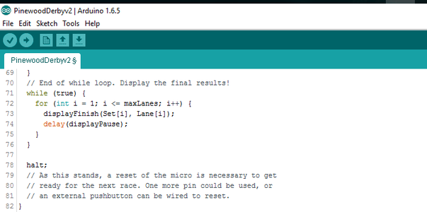
Finally, the sketch loops, displaying the finish order over each lane, by blinking LEDs. First place blinks once, second place blinks twice and third place (guess?) blinks three times.
<p>// End of while loop. Display the final results!<br>  while (true) {
    for (int i = 1; i <= maxLanes; i++) {
      displayFinish(Set[i], Lane[i]);
      delay(displayPause);
    }
  }</p>
To start a new race, press the reset button on the Arduino. If you would prefer, it’s possible to add a button to the Arduino to reset for the next race from another location.
The Arduino sketch is attached.
Attachments

Step 14: Fini!
I was a Cubmaster for my son’s pack and always wanted to automate the finish line at our Pinewood Derby. There was a risk at “eyeballing” the finishers that controversy might erupt. I started way back then with discrete 7400 Series TTL logic and never finished. Today, with the advent of small affordable microprocessors, it is much easier.
This solution is bare bones simple. So much so that the cubs could probably do it themselves. So if you are not in for all the bells and whistles, take a look at my project. It might be just perfect for you!


