

Introduction: Simulated Sports Scoreboard


I am the theatrical technical director for a local high school. Their winter production was “Disney’s High School Musical”. During meetings with the director, he said it would be cool if he could have a scoreboard. I excitedly replied that I could make one that worked by remote control. Warning: be careful what you promise.
This Instructable describes how I constructed the scoreboard. It wasn’t really an operating scoreboard, but one that simulated the requirements of the championship game within the play. Simply, I constructed an Arduino controlled, 4-digit display constructed from LED strips. The remote control only used one channel, to cycle through a set of pre-programmed scores.
There was a strict production deadline. As such as I ran into problems, I made compromises toward meeting the dates. So, this Instructable is more than my typical construction article. It documents mistakes as well as successes. At times, it diverges into the problems I encountered, what caused them and how to avoid them happening to you.
In particular, most of my issues revolved around the PCB board construction. I hope my experience will prove of value to help you in making your own custom PCB boards.
Also, my sketch for the Arduino produced a noticeable flicker, which could have been avoided by better programming practice. In this application, this wasn’t a critical flaw. However, I provide thoughts as to how I would have avoided this problem.
The display is created by displaying each digit for a short period of time, so that the eye sees all four being shown. This is known as multiplexing.
Note: If you are unfamiliar with 7-segment displays, they are in the shape of a block ‘8’. Each segment is lettered a-g. ‘a’ is the top segment and then continuing clockwise the segments are labelled b-f successively. ‘g’ is the cross segment. By illuminating different segments, the digits 0 through 9 are created. For example, a ‘1’ is displayed by illuminating segments b and c.
Step 1: Materials

- Remote Control module, single channel, relay output
- Custom Display Driver boards (qty 4)
- 12VDC 5A 60W DC Power Supply
- Arduino Mega 2560 kit (w/ USB cable and power adapter)
- 22 Gauge hookup wire, 8 colors
- TO-220 Heatsink kit (10 pcs)
- 2N7000 MOSFET (qty 32)
- NDP6020P P-Channel MOSFET 20V 24A (qty 4)
- TO-220 Heat Sinks (qty 4)
- 1/8” 10K Resistors (qty 15)
- 8-pin Headers (optional, qty 8)
- 44”x32” acrylic sheet
- ¼” Luan plywood (44”x32”, 17”x44” & 12”x44”)
- 1”x2” Pine Boards (qty 4)
- Misc. hardware
- Solder
- Solder wick (optional)
- Painter’s Tape (1” & 1-1/2” widths
- Vinyl Letters, 2-3” high
- Hook and Loop fasteners (tape)
- Extension cord (25” or longer)
Step 2: Electronics Block Diagram


The entire project is constructed of eight modules. They are
as follows
- · 9VDC power adapter – Arduino (commercial product)
- · 12VDC 5A power adapter for the remote-control receiver and the LED strips (commercial product)
- · Remote control receiver & remote (commercial product)
- · Arduino Mega 2560 (commercial product)
- · Digit Drivers (custom PCB)
- · 7-Segment Digits
And the non-electronic components are:
- · Scoreboard Front
- · Scoreboard Rear
The Remote control is powered with 12VDC and its internal relay is used to switch ground to an Arduino I/O pin. The pin is configured as INPUT_PULLUP, which keeps its value high until the remote control switches it to ground. This is important. If your microprocessor can’t do this, an external resistor to Vcc will be required.
The Arduino is powered by an Arduino power adapter (wall wart) at 9VDC. Its ground is connected to the 12VDC ground for driving the digits.
Seven pins of the Arduino are set to display the proper segments for each digit. Four additional pins are used to multiplex the four digits. This is done to avoid using 28 pins just for the display. It also simplifies the wiring and display driver design.
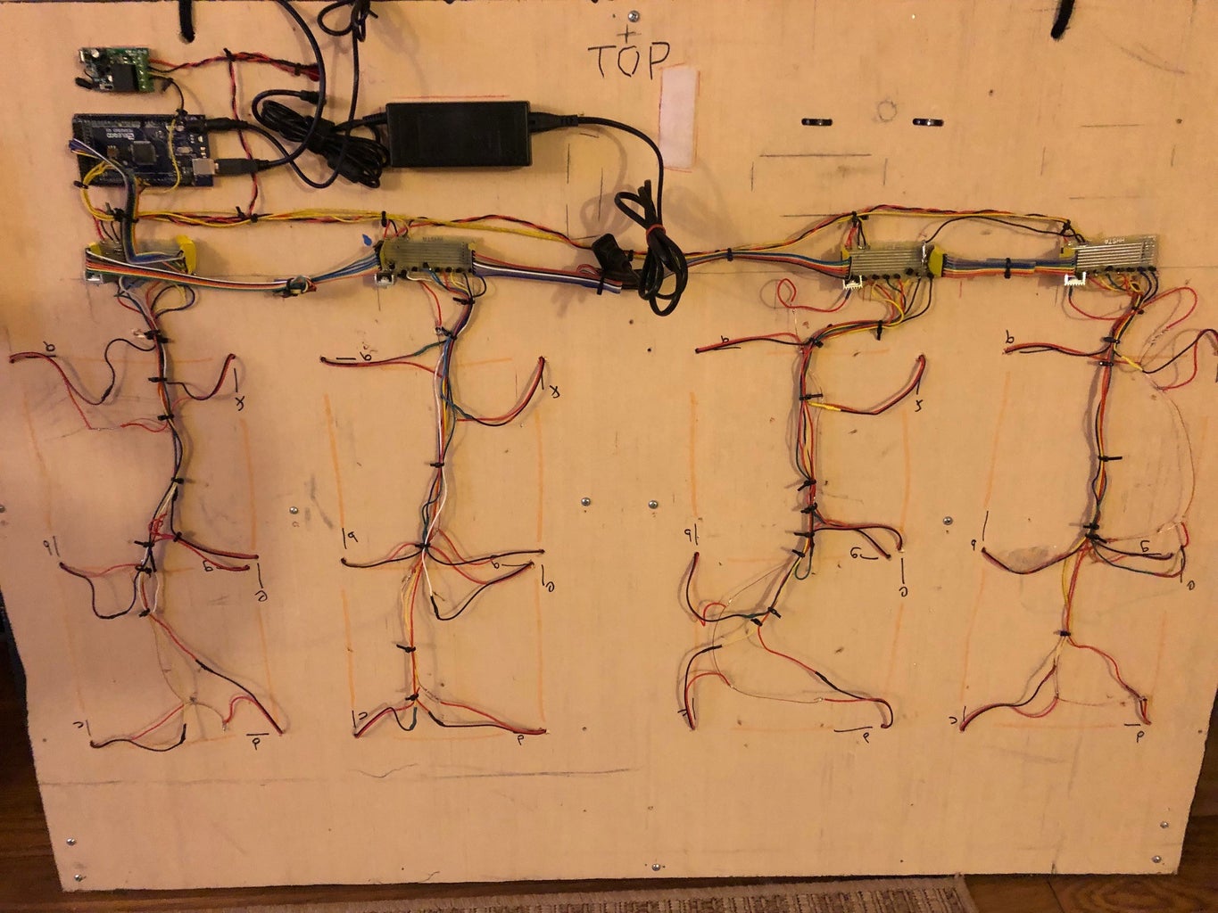
The second picture shows how the component modules are attached with self-adhesive hook & loop fasteners to the back board.
Step 3: Design of the Scoreboard


I wanted something about 3’ by 4’ for the display. My final size selection was based on a standard size acrylic sheet available at Lowe’s. The LED strips I purchased had an LED about every inch. If one segment was 6” (resulting in a 8” by 16” digit), I could place four digits with an extra space between each pair.
This left me space above and below the digits for lettering on the scoreboard. I did not make this space equal, because it looked better with more space on top.The front layout of the scoreboard is shown in the picture below.
A backing piece of ¼” luan plywood was also cut. 1”x2” pine was used to frame the backboard, as well as separate the digits, so that light from one digit did not splash over to the next. You can see the backing board with the LED strips attached in the first picture
See the layout diagram for the backboard construction in the next step.
Step 4: Making the Backing Board

Cut a piece of ¼” luan plywood to the same size as the acrylic sheet, in my case that was 44” x 32”.
Paint the digit area white. The digit area is 10” from the top and 6” from the bottom, for an area of 16” x 44”. Paint an area slightly larger.
Once the paint is dry, use 1”x3” pine to frame the board. I used glue and screws, as the frame must be strong enough to hang the scoreboard from a scenery bar. Also, there are four interior stiles which separate the digits and keep light from bleeding into an adjacent digit. See the picture for the layout.
Now that the frame and stiles are attached, use 1-1/2” wide painting tape to mask the actual digits. The tape should form a block ‘8’ digit/character.
Before continuing, drill seven 1/4” holes in the corners of the digits. These are used to power segments a-f. The cross segment needs two holes. The second hole is for segment g.
Once the digits are all masked, paint the entire backing board assembly black. But, do not paint the rear of the board. It should remain raw wood in order that hook and look fasteners can adhere in order to attach the electronics.
Step 5: Making the Front Board

The front board is created by sanding one surface of a sheet of acrylic plastic. The sanding is done for two reasons. First, to diffuse the LEDs behind it for displaying the digits. Secondly, it allows paint to better adhere to the plastic.
The next step is to mask the digits using 1-1/2” wide painters’ tape. Refer to the next step to get measurements to properly place the masking. You may have to use a razor knife (or rather, will have to use) to trim the corners, in order to create a sharp mask. Pay extra attention to rubbing down the edges of the tape to keep paint from seeping under the edges. Rub until you think it’s all set and then rub some more.
Once the white paint has dried, mask a border around the outside edges with 1” painter’s tape. Rub as obsessively as you did before. Secondly, apply vinyl lettering for the school and team names. Rub, rub, rub.
Once the front has been masked, apply your front coat of paint. For “High School Musical”, it was red.
Let the paint dry overnight. Then carefully peel all masking from the front. I have found that sometimes running a razor knife along the paint edges assists in removing the masking.
Step 6: Designing the Display Driver
We need to carry the seven signals for the segments on each digit. These same seven signals carry across all the driver boards, so are excellent candidates for a bus design.
Each board also has one signal to determine when it is being displayed (as in the multiplexing scheme, each digit is quickly displayed in turn).
Connecting orthogonally to these lines are traces which run to the top of the board and drive the FETs used to power the LED strips. The seven FETs switch the LED strip common to ground. Each strip requires 0.12A. The 2N700s I used can switch up to 0.2A.
We require something to switch the high side of the LEDs. I used two additional FETs. One is used as power FET that must switch at a minimum 0.85A. I use cascaded FETs here in order to switch the 12VDC high side. A 2N7000 is a logic level MOSFET, that is used to trigger a power FET, which switches 12VDC at more than 0.85 amps.
The FETs require pull-down resistors, to switch cleanly. 10K resistors are used; two are used in the high-side switching and on one board, all seven bus lines/traces are terminated each with a 10K resistor.
Step 7: Designing the Custom PCB for the Display Drivers

The software I’ve used in the past include ExpressPCB and DipTrace. ExpressPCB is simpler (but at what cost?) and they offer a mini-board option for a good price. DipTrace is harder to learn and you have to find a PCB board manufacturer to make the actual board. Additionally, there are steps necessary to create the required file formats for the PCB manufacturer. I selected ExpressPCB for its ease of use. But as you are about to find out, the cost must consider the time spent later debugging the final result.
A PCB design includes three elements. Top Layer. Bottom Layer. Silkscreen layer. The latter is optional and wasn’t on my final board, but I included it for documentation purposes.
The final board was thus a two-sided design. The back was used to route traces so that they didn’t have to cross over others on the board. I also designed the board with a ground plane, which helps the circuit operate more reliably.
Step 8: Component Specifications


When laying out the PCB, it is critical that you select the proper hole sizes as well as know exactly how much space each component occupies on the PCB. I have attached pictures showing excerpts from the component datasheets. You need to have accurate measurements to design with the proper trace and pad spacing. What looks like sufficient clearance in the design program, may be insufficient during manufacturer. My boards are tinned and the thickness of the tinning layer can create shorts.
Attachments

Step 9: Schematics

This may be obvious, but not necessarily. First, you need a schematic. There are several free programs which you can use. I use ExpressSCH as it is a sister program to ExpressPCB. It is used to guide you in making a custom printed circuit board. Make several copies, as they become marked up during the process.
I often use the design program and try several different designs. Circuits can be divided into different functional areas. I circle them on my schematic. Then, I start with my input circuitry on the left and begin to place components. Then, I proceed to each following area.
Step 10: Routing

I try to design the board so that inputs are on the left, outputs are on the right and power components are on the top and bottom. Specific designs may call for other arrangements, which will be obvious in the requirements phase or become obvious during the layout phase.
This is where the datasheet study you have done becomes important. Make pads and holes to fit the components. Adjust trace widths depending on the current they are expected to draw. Ensure that the hole spacing will accept your components.
Print out the design and study it. Look for patterns to guide you in moving components about on the PCB design, to save space and reduce traces. I then make a copy of the PCB file and start modifying it per the changes noted.
After you have laid out the components, place a printout of the schematic and board side by side. For each line in the schematic, identify its location on the PCB. Mark both with a marker to indicate they are properly connected. Once you complete this step, there should be nothing unmarked on either diagram.
If you are satisfied, now is the time to run a design check (Yes, I know I admitted to skipping this step, but look what trouble it brought me. The design check will assure you that all clearances are within specification, and no unintended shorts will occur.
I sometimes repeat these checks twice, to be sure all is copacetic. Because once you manufacture the board, you are committed to your design. I ended up ordering two batches because of a mistake (which should have been avoided) and then still had problems.
Step 11: Finalizing the PCB Design
At this point, I am sure that the layout is correct. If mounting holes are needed, I’d add them at this point. I also add any additional labelling that I desire before sending it to be made.
Step 12: Wiring the 7-Segment Digits


The LED strips came as one long roll of 300 LEDs. They have an adhesive backing. The strips can be cut down, but each smaller strip needs wires to be attached. My layout resulted in my needing 28 strips of 9 LEDs each. Note that when cutting the LED strip there is usually a requirement that the resulting strip contain some multiple of LEDs. The strip I used meant that I had to cut it on a multiple of 3. As far as wiring the smaller strips, I purchased connectors that press fit on each strip. They can be seen in the pictures below. Be careful to ensure that red goes to the positive LED connection and black goes to its ground. There are small + signs printed on the strip to aid in doing this properly.
After cutting the strips and attaching the connectors, I adhered them along the segment centerlines on the backing board. The connecting wires were fed through the ¼” holes drilled previously. I shouldn’t have to mention this, but you did place each strip’s connector next to the appropriate hole? I marked both sides of the backing board with the segment letters. This also avoided mix-ups because of the right to left swap of locations on the front and back.
For each digit, I used bare copper wire to solder all the red connections together. A short piece of wire was added to connect to the driver board.
Then, I used some 22-gauge solid insulated copper wire in seven colors to connect each segment individually. I created a color code chart so that connections to the display driver boards could be made reliably. In the last picture the color is off but note where the connections are finally made to the display driver board. Also, note that the wires are zip-tied together for neatness and that all joints are covered with heat-shrink tubing. These points are circled in the picture.
Step 13: Construction of the Display Drivers


Each display driver board requires eight 2N700 NPN FETs. One for each segment, and one to drive the power FET used to switch power to the entire digit. This is how the segments are multiplexed. Note two type of FETs are used. Their connections are critical, specifically the location of the source, drain and gate pins. The picture below illustrates the pin connections for each type of FET. Also, the diagram of the custom printed circuit board locates these pins on the silkscreen layer.
Solder seven 2N7000 FETs along the top of the board, observing the orientation of the parts. There is also a 2N7000 FET on the right of the board. Notice that the orientation of this part is different from all of the others.
There is a power FET in the upper right corner of the board Again, be careful with its orientation. Also, note that the order of pins (source, drain and gate) is different from the 2N7000s. Also, I attached a heat-sink to each power FET. At this time, solder the two FETs, and their associated resistors into place.
The first header is used to connect to the Arduino Mega. Segment a connects to pin 40; segment b connects to pin 41, etc. The eighth pin on the header connects to a ground pin on the Mega.
The seven segment data traces are terminated on each end of the board with headers (or not! Read on). Eight-pin headers are used. Where the seven lines are connected, there is an eighth pin. This is used to tie the digital (Arduino) ground to the display ground. Once again, it is only used on one board, the first in the chain. Internally on the display driver boards, it is connected to each subsequent digit. You can choose to hard-wire these bus connections. I didn’t, but wish I had. The next paragraph describes the problem.
The headers are optional as mentioned above. 22-gauge wire can be used to daisy chain these connections. I used the headers, but during final assembly, the ribbon jumpers were of an odd size and I had to double up the ribbon cable in places. This is not good design practice, as these cables add capacitance that might affect the FETs performance. I was in a quandary. I like to connect modules with jumpers, as it allows me to remove modules for troubleshooting. Also, with the time constraints, I didn’t feel like soldering an additional ~50 wires. In the PCB design phase, the holes for the headers were sized to use 22-gauge wire optionally.
There are two 10K 1/8W resistors used to pull up the input to the power FET and pull down the input to the driving FET. There are other resistors used in one special case, as described below. These resistors are located on the right side of the board and must be soldered in place.
On the right are several pads. The data lines for the segments need to be terminated to ground. Otherwise, the FET may not operate correctly and refuse in some cases to turn off. I mention this specifically, because the resistors used to terminate the data lines are NOT needed on each display board. They are only installed on the last board in the chain. Place and solder these carefully, as they are squeezed in between the traces used for the segment bus.
Finally, the board must be connected to the LED strips. Along the top are 7 holes for each digit segment and another hole for the power connection. These were soldered directly, in the manner described in paragraph four of this step.
So, we have placed the FETs for each segment and one power FET for the digit. Pull-up and pull-down resistors have been soldered in for the power FET section. We have wired the digits to the board. All that is left is to supply power. There are two sets of two holes for that purpose, two each for 12VDC and Ground. The first hole of each set comes from the power supply on the first board or the previous board on all subsequent display driver boards. Thus, all four boards have 12VDC and ground daisy-chained between them.
Step 14: Oops!


I use either DipTrace or ExpressPCB to make my custom printed boards. I use the latter for quick projects as they have an inexpensive option for small projects. One of these two solutions have a design check. This project didn’t qualify for ExpressPCB’s miniBoard Pro option; the one I usually use. It didn’t have the design check without downloading additional software.
Mistake #1: I am used to the solder mask with the ExpressPCB miniBoard Pro option. I cut corners and didn’t add it in. Soldering adjacent pads became difficult.
Mistake #2: When I received the boards, several pads were shorted to ground. That is because I mistakenly placed them, trusted my eyes on a computer screen and decided that I didn’t have time to download the software. The pictures below illustrate my problem.
Mistake #3: Oh crap. I forgot to specify the correct size hole for the power FETs.
Step 15: How to Fix

First, the lack of a solder mask problem. I used to have excellent soldering skills, but with age and the onset of slight hand tremors, I’m not as good as I used to be. Without the solder mask, my joints were sloppy. I ended up going over each joint with soldering wick and removing any excess solder.
I recommend using a solder mask whenever possible, unless you are very sure of your soldering skills.
Then, I tackled the shorts on the board.
I drilled out ALL the pads that had the shorting problem. Remember, that most of them were included for convenience when constructing the board and that most were replicated for ease and not used. So, away they went.
I had a similar problem with the pull-down resistor on the driving FET. I cut it out and operation wasn’t adversely affected. Otherwise, I would use the next trick.
The terminating resistors on the bus WAS critical. So on one board, I masked the traces with strips of duct tape and soldered the termination resistors directly to the traces. Then, I soldered all seven resistor leads to a short piece of wire and connected it to an unused ground tab. Its UGLY, but it works.
Step 16: Better Design for the PCB


I went back to the PCB design program. I calculated that 1/8W resistors would work, looked up a datasheet and sized the pads to the minimal diameter. This gave me more room on the board, especially between the bus traces. Then I checked each and every pads coordinates on the board and manually lined each and every connection up, both horizontally and vertically. The resulting design is shown in the picture. Note there is plenty of space between the pads and traces, as indicated by the arrow
Step 17: Major Assembly

There are a lot of connections to be made.
First, I used hook and loop to attach a 1-to-3 household plug adapter to the backing board. Zip ties were inserted through holes to one side of the three plug adapter, to attach an extension cord permanently. Then, the 9VDC and 12VDC adapters were plugged in.
The 9VDC adapter was connected to the Arduino Mega.
The 12VDC adapter was connected to a female jack, Then, wires were run to the remote-control module and daisy chained along all four display driver boards.
The Arduino and remote-control module were added. A connection to the common contact of the relay was made to the Arduino ground. Themn, the remote-control NO pin was connected to pin 2 of the Arduino.
Then, two sets of wires were connected from the Arduino to the display driver boards. Pins 4-6 were connected to the “dsel” or digital select pin on each display driver board. Pins 40-46 were connected to the a-g pins on the first driver board. These seven signals are then daisy-chained to all remaining digit drivers.
And don't forget! One wire must connect from the first board's ground pin on the header row, to a ground pin on the Arduino Mega.
We’re all wired up. It was easy to describe, but there are over 80 connections to the boards alone, with another 56 on the digits. Wow! Careful construction is necessary. Fortunately, I did not have any wiring errors when I powered the whole thing up.
Step 18: Software

The Arduino program used to drive the scoreboard in the actual production of “Disney’s High School Musical” is a slightly advanced Arduino sketch.
It multiplexes the score digits, changing the score per a pre-programmed sequence every time the remote-control button is pressed.
My programming style is to start with a high-level operation concept and first designing the data structures necessary. Hence, my following description will start with a lot of detail of the data used in the sketch.
Step 19: Sketch Structure
- The sketch starts by defining the data structures to be used
- Then, the setup portion initializes the I/O pins.
- Subsequently, the loop displays the current score and checks for a request to change the score.
- Finally, there is code to read the pin assigned to the remote control and debounce the input (as the remote-control module controls a relay for its output. The relay is a mechanical output and hence subject to electrical bounce).
Step 20: Data / Constants
The score sequence is stored in a multi-dimensional array, four elements wide by the number of scores long. The value of each cell in the array is the digit to be displayed for the corresponding score, from 0-9. Note the value of 10 indicates that the digit is shut off. You can read the scores vertically. Hence, in the code below, all digits display an 8 (to test the display) and then all digits are shutoff to begin the show. The first score shown in the scene is Wildcats - 87, Visitor - 92!
const int countScores = 9;
const int scores[][countScores] = {
  {8, 10, 8, 8, 9, 9, 9, 10, 9},
  {8, 10, 7, 9, 5, 7, 9, 10, 9},
  {8, 10, 9, 9, 9, 9, 9, 10, 9},
  {8, 10, 2, 4, 7, 7, 7, 10, 7}
}; // end scores definition
I use macros to define commonly used references, to make the code easier to read. The next section of the data definitions define some references used in the display as well as in the debounce routine.
#define segOn HIGH
#define segOff LOW
#define digitOn HIGH
#define digitOff LOW
#define PUSHED false
#define NOT_PUSHED true
#define WATCH_BUTTON true
#define IGNORE_BUTTON false
The next section defines variables and values used in the debounce routine. I’d like to take a moment here to note that I define global variables, so that when tuning the sketch, I have a common location to make adjustments, rather that searching through the code, looking for values to be changed.
unsigned long buttonWaitInterval = 5000; // in MICROSECONDS
unsigned long digitDisplayTime = 1; // pause per digit, in us
const int BUTTONpin = 2;
unsigned long previousMicros = 0;
boolean previousButtonState = NOT_PUSHED;
boolean debouncedButtonState = NOT_PUSHED;
boolean bounceState = false;
The next section defines constants used to reference individual segments of display digits. When debugging this sketch, I found it easier to refer to a-g as these are how a seven-segment display is defined, rather than having to remember the bottom segment, d, is equal to 3.
const int a = 0; const int b = 1; const int c = 2;
const int d = 3; const int e = 4; const int f = 5; const int g = 6;
The next definition is of an array, ten rows wide and seven values ride. Each cell defines what a digit looks like. For example, the digit 5 consists of segments a,c,d,f and g being on. Look at the 6th row (corresponding to 5) and note the segOn and segOff sequence.
const int digits[][7] = {
  {segOn,  segOn,  segOn,  segOn,  segOn,  segOn,  segOff}, // 0
  {segOff, segOn,  segOn,  segOff, segOff, segOff, segOff}, // 1
  {segOn,  segOn,  segOff, segOn,  segOn,  segOff, segOn},  // 2
  {segOn,  segOn,  segOn,  segOn,  segOff, segOff, segOn},  // 3
  {segOff, segOn,  segOn,  segOff, segOff, segOn,  segOn},  // 4
  {segOn,  segOff, segOn,  segOn,  segOff, segOn,  segOn},  // 5
  {segOn,  segOff, segOn,  segOn,  segOn,  segOn,  segOn},  // 6
  {segOn,  segOn,  segOn,  segOff, segOff, segOff, segOff}, // 7
  {segOn,  segOn,  segOn,  segOn,  segOn,  segOn,  segOn},  // 8
  {segOn,  segOn,  segOn,  segOff, segOff, segOn,  segOn},  // 9
  {segOff, segOff, segOff, segOff, segOff, segOff, segOff}, // Off
}; // end segment definitions
The next definitions define the starting pin for the segment and digit control. Note for example to address the bottom segment, the sketch references “segmentBase + d”.
const int segmentBase = 40;
const int digitselectBase = 4;
And finally! (I did warn you that I personally like to spend a lot of time defining data), I define a couple of constructs that I personally use. The first is “Forever”. It is an alias for “true”, that I use in an outer loop to repeat indefinitely. Later, you will see a line of code that states “While (Forever);”.
The second line is similar. When I want a sketch to stop executing, I write a line that says “Halt;”. It lets me know when reading the sketch, that this is where I stop.
const boolean Forever = true ;
#define Halt while(true)
Step 21: Setup / Initialization
The use of all digital I/O pins on the Arduino must be initialized according to their use.
The button pin for the remote control is an input. It has to be defined with the INPUT_PULLUP option, because the input to it will be normally floating.
The digit select pins and segment select pins are all output pins.
I also initialize the serial pins of the Arduino, because I use them while debugging. Normal operation doesn’t require this.
void setup() {<br>  Serial.begin(9600);
  pinMode(BUTTONpin, INPUT_PULLUP);
  // Serial.println("Control initialized");
  for (int Pin = segmentBase; Pin <= segmentBase + g; Pin++) {
    pinMode(Pin, OUTPUT);
    digitalWrite(Pin, segOff);
  }
  // Serial.println("Segment control initialized");
  for (int Pin = digitselectBase; Pin <= digitselectBase + 3; Pin++) {
    pinMode(Pin, OUTPUT);
    digitalWrite(Pin, digitOff);
  }
  // Serial.println("All segments off");
} // end setup =========================================
Step 22: The Good Stuff
Now we get to the main code. We set up some variables that are only used in the main loop.
  int score = 0; // which set of scores are we displaying?
  int lastdigit = 0; // The last digit displayed. Recalculated in loop
  int digit = 0; // Just define the variable
  int segment = 0; // Just define the variable
This time, I’ll describe the operation at a high level. Then, you can follow the comments in the code to see how this is done.
We loop forever. Each time through the loop, we display each of the four digits in order. To multiplex them, we turn off the previous digit, set up the next digit and turn it on for a brief of time. Before we repeat this process, we check to see if a request to change the score is received. The code to do this follows.
while (Forever) { // multiplex digits

    // Display all digits
    for (digit = 0; digit < 4; digit++) {

      // turn off last digit
      lastdigit = digit - 1;  // calculate last digit displayed
      if (lastdigit < 0) lastdigit = 3;
      digitalWrite(digitselectBase + lastdigit, digitOff);

      // turn on next digit
      for (segment = a; segment <= g; segment++) {
        digitalWrite(segmentBase + segment, digits[scores[digit][score]][segment])};
      digitalWrite(digitselectBase + digit, digitOn);
      delayMicroseconds(digitDisplayTime);

      // See if a command to change score was received
      updateButton();
      if (! debouncedButtonState) {
        while (debouncedButtonState == LOW) updateButton();
        score++; // activate next score
        if ( score == countScores) {  // all scores have been shown
          AllSegmentsOff();
          AllDigitsOff();
          Halt;
        }
      }
    } // end loop through digits
  } // end multiplexing digits
} // end void loop ======================================================</p>
Step 23: Debounce Routine
Ok, to be honest I didn’t write this. I borrowed it from a sketch online. The only debounce routine I had in my library was a multi-press decoding/debounce routine. I didn’t need that. I’m including the listing here for completeness. It works. I can’t support it.
void updateButton() {<br>  if (bounceState == WATCH_BUTTON) {
    boolean currentButtonState = digitalRead(BUTTONpin);
    if (previousButtonState != currentButtonState) {
      bounceState = IGNORE_BUTTON;
      previousMicros = micros();
    }
    previousButtonState = currentButtonState;
  }
  if (bounceState == IGNORE_BUTTON) {
    unsigned long currentMicros = micros();
    if ((unsigned long)(currentMicros - previousMicros) >= buttonWaitInterval) {
      debouncedButtonState = digitalRead(BUTTONpin);
      bounceState = WATCH_BUTTON;
    }
  }
} // end debounce routine =====================================
Step 24: All Stuff Off
Additionally, there are two functions I wrote, just to keep their code out of the main routine and make it easier to read. They normally wouldn’t be required, as I only used them once. But as I say, it made the main loop easier to read.
void AllSegmentsOff() {<br>  for (int Pin = segmentBase; Pin <= segmentBase + g; Pin++) {
    digitalWrite(Pin, segOff);
  }
}
  void AllDigitsOff() {
    for (int Pin = digitselectBase; Pin <= digitselectBase + 3; Pin++) {
      digitalWrite(Pin, digitOff);
    }
  } // end all stuff off =======================================
A text copy of the Arduino sketch is attached to this instructable.
Attachments

Step 25: Final Assembly
Before the scoreboard was hung in the theater, two protective panels were added.
A 17” x 44” piece of luan plywood was placed over all of the digit wiring, using small nylon spacers to provide room for the wiring.
A 12” x 44” piece of luan plywood was placed over all of the electronics to protect it. I did make a cutout to clear the extension cord which was plugged in.
Two 3/8" holes were drilled through the acrylic and back board through which black cord was threaded. This cord was used to tie scoreboard to the pipe from which it was hung. (This pipe raised and lowered the scoreboard above the stage into the audience' view.)
Step 26: Operation
The scoreboard’s only reset option was to unplug the unit for a short time, then plug it back in. This had to be done before each performance. The score sequences in the code started with all digits showing 8s. Then the remote was pressed and all digits went dark. The next sequence started the scores in the scene. It operated perfectly.
Step 27: Final Thoughts

There is a slightly noticeable flicker to the display. The code is not as efficient as it could be. To improve it, I wouldn’t use "for" loops to set/reset the segments. The Arduino has port I/O in its architecture, and I would use that so all seven segments would be set in one operation.
Also, while the code only displays a pre-programmed sequence, a more general scoreboard could be made simply by changing the sketch and using a four-channel remote instead. I leave the execution of that design to the reader.

Participated in the
PCB Contest


