

Introduction: Invasion of the Steampunk Robot Lights


In the middle of the night, a strange unearthly light was seen glowing where no light had been before...
Step 1: At First No One Realised They Were Here...


No one knew when they first arrived, it could have been before life on earth, it could have been tomorrow. For millennia maybe something disappeared, or mysteriously got fixed, but that got blamed on the pixies and faeries of children's tales and folklore. Eventually though, worldwide, a pattern was emerging, unexplained sightings of curious creatures that lit up at night, hiding in plain sight, disguised by their familiar but disparate component parts. Slowly, over untold centuries, sightings and evidence built up, a pattern emerged. Talk spread of an alien invasion, abductions and unexplained phenomena, until finally secrets, long held buried by unnamed agencies within the deepest bowels of governments, started to leak out. Rumours of another parallel world, one with life forms not based on carbon and oxygen but metal and electricity and of a hidden bridge between their reality and ours. Rumours of unknown visitors, sensed but never clearly seen. But, as more became known to the general population, so the fears began to rise and turn to panic, fuelled by a sensationalist media and a dread of the unknown. Where had they come from? Why were they here? What was their motive? What will I have for tea? And then, finally, one appeared...
To Be Continued!
Step 2: I've Had an Idea...

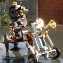
Step 3: ...Let's Make a Steampunk Robot Light!


According to Hot Chocolate, it started with a Kiss, from rock to soul. Maybe for them it did, but for me it started with a bulb. Each to their own I suppose. I knew as soon as I saw it on the shop shelf begging me to buy it that I was going to use it somehow as a brain, hopefully brighter than the one I was given. It reminded me immediately of a combination of the Martians in Mars Attacks! and Robby the Robot from Forbidden Planet (who also guested in Lost in Space). The end result also unintentionally had a bit of Huey, Dewey, and Louie in there, the maintenance robots from Silent Running, not the half-naked ducklets of Disney. That would just be ridiculous- what kind of a duck goes around with a lamp for a brain? Not a very bright one, that's for sure as everyone knows water and electricity don't mix. So, there goes my idea for a water powered battery you can recharge from any tap.
Also, don't go expecting a great series of logical instructions because I built this over a few months with gaps in between and I also don't usually take photos when I'm actually building something anyway. Hopefully you'll find my drawings useful, but this is as much about the U-turns and additions that came along as I was building this up. This isn't a Michelin Guide but a Jack Kerouac laissez-faire go with the flow, man, guide to get you from here to there on a rambling yellow brick road with a spinning compass, rather than a map and GPS co-ordinates. This is old school design by the seat of your pants, not a filament of plastic or a CNC machine anywhere to be seen, just old fashioned suck it and see with a bit of "That doesn't taste right, I think I've put in way too much salt again!" plus my trusty bench grinder to add some sparks, needed or not.
Step 4: Supplies


Many of the parts I used came from my junk pile but the following were bought:
A Suitable LED bulb: The one I bought is an LED but it has a finely etched plastic cylinder that makes it look like a filament lamp. Manufactured by TCP, it's the only company I've seen making LED filament bulbs in this way. It gives a much more interesting result than a normal LED filament bulb and the lines are much finer, but without any of the heat and power issues of a decorative filament lamp.
A Metal Surface Mount Switch Box And Blanking Plate For The Body: Some surface mount switch boxes already have holes drilled in the back (which becomes the front) but the one I bought didn't have any (MK 891 ALM). This is better if possible, but if not just fill in the holes before painting or use them as part of your design.
A Suitable Switch: This is dependent on what you want the finished robot to look like. You could use a toggle switch, a rotary switch, an inline cord switch or no switch if you want to use either the mains socket or a smart bulb. The only criteria are that it fits and is rated at the voltage and current you will be using, 240v AC in my case with a very low current so any mains rated switch will work fine. This one I got from Ebay because it didn't take up much room, had flying cables attached and it was in keeping with my design. You turn it clockwise and every 90degs it turns the light on or off. I suppose you could call it a smart switch as it always seems to know to switch the bulb off if it's on or on if it's off. I'm not sure how it knows but I suspect it has either a current sensor in it or some sort of magic light detector which tells it what state the lamp is in.
A Conduit Spacer Saddle: This will be sawn in half to become the feet.You won't need a robot horse to go with it.
Two Pairs Of Small Curved Needlenosed Pliers (Or Any Other Pliers Shape You Like): These will be used for the arms and the hands/claws/grabby things at the end of the arms. They can be the cheapest you can find, they don't need to be quality ones. In fact, the cheaper the better as they'll be easier to shape and drill probably. I tried getting a matching set of right and left handed ones, but in the end I could only find right handed ones and had to flip one over, but I don't think anyone will notice. Or you could fashion arms out of a piece of rod or thick wire and use small crocodile clips as the claws.
3 Core Cable/Flex, Plug And Connectors: I won't be going in to details on the wiring on the grounds that this is a simple light switch circuit so if you already don't know how to do it, find out properly from someone who does. The only thing you need to make sure is that you earth the metal body (hence the 3 core cable, two for the bits that can kill you, one for the bit that can save you) and use a suitable fuse in the plug (3A). It's always good to realise that if you don't know what you're doing, electricity has a subtle but surprisingly quick and effective way of teaching you about the risks by giving you a free death certificate, which can come as a bit of a shock if you're not expecting it.
A Suitable Unswitched Bulb Holder: It just needs to be a lampholder that matches your bulb and fits inside the box. However, I usually use bayonet/BC bulbs as the lampholders are less bulky and IMO better constructed than the typical Edison screw/ES lampholders. I used a brass one because it fits in with the general aesthetics but they are also more bomb-proof in metal. No point getting a switched one, the switch will either be inside the box or not that conveniently placed anyway once the head is added, hence the separate front switch.
Cabachon Eyes: These are glass, like a magnifying glass but flat on the back with a bonded-on photo of an eye. The ones I used were alien and 25mm across but you'll find lots of different sizes and types, depending on what you want it to look like. Be creative though, you could use marbles, beads or build metal eyes using washers, etc. You could even take a photo of your own eyes and use those, but I didn't want my droid to have bloodshot cross eyes and be wearing glasses. And who says a robot has to have two eyes? In this case, me.
A "Hi, Kia!" Glattis Brass Coaster: When I first made the lamp it kept falling over so it was obvious it needed a base of some sort. These are actually steel disks with a brass skin and a rubber bottom but they are relatively cheap and make great bases, hence the basis of my use in this design. It now doesn't fall over, based on current observations, unlike my rubber bottom which seems to fall over repeatedly. In fact, it works so well I'm thinking of screwing a couple of them to my shoes for use in icy weather, but maybe I'll leave that for another Instructable.
Step 5: Creating the Main Body


The main body is made from the surface mount switch box. I actually used the switch box back to front as I wanted the switch to be fixed to the main body part so the rear which is usually used as the part fixed to the wall becomes the front of the robot. This also gave a smoother seamless front with no fixing screws on it.
The only hole you actually need to cut out at this time is the lampholder hole at the top. The rest are best cut out once you've created the other pieces and know where you want them to go. To cut out the hole for the lampholder I used a stepped drill. These are brilliant for cutting holes and easier to use than a hole saw because they cut out a range of holes without having to necessarily know the size needed, plus you don't have to mess about swapping the rings. I also think they are easier to use in a normal portable drill.
Once you've drilled out the lampholder you can temporarily put it in place to see where you can mount your switch if you are adding it to the front. As you can tell from the photo, the other advantage of the switch I used is that it is minimum size inside, being pretty much the same size as the hole. I'm sure there's a pun there about the whole being the same size as the hole, but I can't think of it at the moment.
I did consider using a rotary switch on one of the arms so that you lifted the arm up to switch the lamp on but decided against it. Still, no arm in trying it if you want to. Alternatively, use a standard light switch and either put it at the front or at the back instead of using a blanking plate.
The brass gauge on the front was simply there for embellishment. It was actually a lock escutcheon in which I put a bit of glass and a fake pointer. I've got a plan to replace it sometime with a small 300v AC voltmeter I've got hanging around just for its visual effect.
Step 6: Making the Feet


The feet were made from the conduit saddle, simply by sawing it in half and then shaping it a bit more into two toes by using either a file or a bench grinder. Depending on what size bolt you will eventually use to attach the feet and body to the base, you may need to drill out the original retainer screw holes in the conduit saddle.
To attach the feet, place the feet where you would like them to be on your robot body and mark and drill the holes. Then put the box onto the Ikea Glattis coaster to mark where these holes are and drill the coaster. The body and feet are then attached with two bolts, which go up through the coaster and legs into the box where a washer and nut are attached to hold the base in place. The brass coasters have a rubber non-slip base attached, so doing it this way with the nut head at the bottom it's easy to cut away some of the rubber to allow the bolt head to sit below the rubber surface. You also don't need to be that exact with the bolt length so if it's a bit long that'll be fine.
Step 7: Making the Arms


The arms were made from two pairs of curved needlenosed pliers but there's no reason you can't use other pliers' shapes, forks (table, not garden) or even just rods with crocodile clips attached.
The pictures show clearly enough what to do, just pull off the plastic grips, then cut one arm right back and the other back to the length you want the arm to be. Then, drill a hole through for the bolt to go through which will be used to attach the arm to the body. Depending on your pliers, there might also be a spring which keeps the jaws open, so just pull that out. Here is the first of the issues you might come across as the arm may be not very big so you will need to use a small diameter bolt. It's not carrying any weight though so no problem there. I used 4mm bolts. The other thing you need to do is to make sure you cut off and drill the opposite sides for the other arm as the two arms need to be mirror images. To save you making this mistake, I first tested it out for you by cutting both the same side. The end result when I attached them was they were accompanied by a thought I then had, something along the lines of "Oh, darned golly gosh, what a silly Billy I've been!" as one claw pointed in and the other pointed out, a bit like Marty Feldman's eyes. Or not like Marty Feldman's eyes, as it's actually preferable for one eye to point in and one to point out, especially if looking left or right. Not too sure about when looking forward, but when I tried it going forward I ran into a door so maybe possibly not. If you do do this by mistake, the arms I mean, not the door, please feel free to add in your own thoughts on the end result, but don't blame me, I did warn you.
Taking the pictures though I came across another problem with just using a nut and bolt to hold the arms in place. They were originally held in place with a bolt inside the body and a nut on the outside. The problem though is that it doesn't hold its tightness and tends to come loose by unscrewing the bolt as the arms are moved and they then just flop down. I could have put a locking nut on but I decided instead to put a clinch nut into the body. A clinch nut is designed to hold the nut in place in sheet metal or similar materials. There are many different types, but the ones I used are designed to be used by pushing it into a hole and locked in place using a special puller which first screws into the nut and then pulls the end inward, collapsing the especially designed collar and holding the nut in place, pretty much the same idea as a pop rivet. The special puller though is expensive, especially if you aren't using it regularly, hence I wondered if it work with a normal bolt. There is however a problem using a bolt. The proper tool screws into the nut, but then just pulls back against the nut. However, if you put a bolt in and keep turning it, it the nut will spin. The solution that worked for me was just to hold the nut at the back using a pair of pliers to stop it spinning as I tightened to bolt up from the front, which was fine as I had access to the back. With the proper tool though, you only need access from one side, like a pop rivet gun. I suspect that instead of using a proper tool, you could also make a make a mandrill by cutting the head off a bolt, screwing that into the bolt and then using a pop rivet gun clamped on to that to collapse the nut.
I've also just come across a really good video at the bottom of this website page showing how to fit a clinch nut without ua special tool just by using a bolt, which doesn't gnarl up the back of the clinch nut in the same way as I did by using pliers to stop it spinning:
https://www.spyderindustries.com/blogs/news/diy-ho...
The last few photos show an alternative arm you can make using a copper terminal connector, some 4mm copper brake pipe and a crocodile clip. These happened to all fit together by just pushing the copper pipe in, but if not feel free to glue or solder them.
Step 8: The Poisonous Gas Tanks


I'd come across these Nitrous Oxide cylinders growing all over the place, so I started to collect them knowing I'd eventually use them for something. In this case, they were just the right size to add to my robot lamp. Construction of these was easy, nothing needed to be welded, soldered or glued.
The tanks are held onto the body using cable ties through holes drilled in the back plate, as shown, which you can now drill as you know where you want them. The pipe I used was 4mm copper brake pipe, but you can use thick copper wire, insulated cable or maybe an old empty plastic biro insert bent with a bit of heat. I first drilled out the ends of the cylinder using a 4mm drill, after checking it was empty although it wouldn't be much of a problem as it won't explode or blast through your roof into space, just whizz out cold nitrous oxide gas, so just wear safety glasses and try not to laugh if it does happen. I then drilled through the dome head nuts, from the threaded side with the same 4mm drill. I cut off some brake pipe and bent it over around a screwdriver and cut it so that it was like a long letter j. The long side is simply pushed into the gas cylinder and the nut was pushed over the other end. The two pipes are then just pushed where I want them. They didn't need any glue to hold them in place, just a lot of pushing. They were a good tight fit, but otherwise just glue them where you want them to go.
Whilst writing this, I did think of taking the pipes up to the bulb instead so it looks like they were going into the helmet/brain. It was simply a case of remaking a pipe with a drilled out dome nut on the end, same as before but different. It's held in place by just being bent slightly to press against the bulb, no glueing needed. As I'd taken some photos before and some after, you can work out which looks better, but I think it's the one going in to the helmet. You'll also notice in the above pictures, there's one without the eyes and face. Originally, this was how I finished it but I decided after that it needed more character.
Step 9: Giving the Robot Character


Once I'd completed the main lamp, I decided it lacked something. And so, the head began. I did consider making eyes of some sort from washers and dome headed nuts, but then I came across Cabochon eyes which turned out to be a brilliant find as they are cheap as chips to boot, unless you buy your chips in a fancy restaurant that calls them pommes frites and serves them on a little square plate with a thimbleful of some fancy sauce that's really just ketchup to normal people instead of a sheet of old newspaper. And for the confused readers expecting me to write in Americanese, chips are what the other manglers/speakers of the English language seem to call fries, and not crisps, which are what they call chips. So, after that digression, back to Cabochons, which are made from glass, domed at the front and flat at the back, like a magnifying glass. An image is then fixed to the back to give a realistic eye. Just do a Giggle search for Cabochon Eyes or Alien Eyes, Dragon Eyes or Martian Eyes.
The next issue was how to design it? I'd like you to think that I designed the face/head from some sort of design process, sketching and developing it until I reached my final aesthetically perfect design. But I didn't. The face/head involved me wandering around my garage looking for bits to inspire me. The starting point was finding the brass winged radiator key which I'd bought earlier to use as winding keys in a fake clockwork something or other. I did think of using one of these on the back of the robot initially but went with the gas bottles in the end. However, I thought these might make something to hold the eyes onto. I did consider using big washers to glue the Cabochon eyes onto but then I came across a red solid rubber ball, almost exactly the right size. This was then simply cut in half with a fine bladed hacksaw, helped by the fact that it had a slight seam around a circumference to follow. These were then attached to the radiator key by drilling a slightly smaller hole through the centre and just pushing them onto a bolt, no glue or fixing needed and the eyes glued onto the front. As a result, the eyes can turn so you can make it a bit more expressive, depending on what you consider a robots expression would mean. It's got two eyes, so I suppose it's thinking in binary. I did notice that if you put a torch behind the Cabochon eyes they glow, so that might be something to use for a future project.
I then needed to work out how to fix it to the robot. I was originally looking for a bracket of some sort, but I then spied an old gate valve from my recently deceased central heating system when my boiler decided it wanted to become a shower instead and also decided it didn't like the kitchen ceiling and did its very best to collapse it. To teach it a lesson I ripped it out which meant I had a very cold Christmas last year, although, nine months later, I have got used to having cold showers. The nut looked about right to go over the lampholder and actually turned out to be exactly the right size, almost designed for the job. Once I'd polished it up, it also fit in with the general aesthetics (project tip: I like to use aesthetics as much as possible in descriptions, because I heard a posh designer say it once and it makes me look like I know what I'm doing. I just wish I knew what aesthetics meant. Or knew what I was doing. I'd also like to squeeze ambiance in here somehow, but I don't think that's remotely possible.). I then drilled a hole through the rim of the nut and one sideways across the base of the radiator key and bolted the two together, topping the bolt with a dome headed nut as a nose. The actual bolt head is on the inside of the gate valve nut, which then caused a problem as it then got in the way of the lampholder. The clever thing to do would be to use a counter sunk bolt, but I wasn't clever enough to have one. So, I just got the trusty bench grinder spinning, a high precision tool all precision engineers use, and ground the head right down, whilst also taking a precision bite out of the brass ring on the lampholder so it didn't feel left out.
It still looked a bit expressionless though without a mouth, so once again I went looking for something suitable. In the end I gave up and used a large penny washer, for which I must have been overcharged as I ended up getting a pack of 10 for 90p. I first drilled a hole in the rim where the nose bolt would go through, leaving the main hole as the mouth. I then also applied my precision grinding engineering skills to this to create the mouth shape, finally sticking a bit of red insulation tape behind it to give it lovely rosy lips. I'm sure you'll get the idea from the diagram. If not, then at least you'll know how I felt doing it first because I didn't have an idea what I was doing either.
You're probably now wondering why I didn't give it ears. I'm just wondering that myself. I'll let you know when I work that one out, but if you do think of a good excuse I can use, please let me know. At the moment I'm left with either having to fall back to using the aesthetics get out clause or the fact that they'd be useless because in space, apparently, no-one can hear you scream. I'm not sure about the second excuse though, as I've been in lots of spaces where you could hear me scream, so I'm not sure that's actually true.
You're probably also wondering why I spent so long explaining this when it's easy enough to tell what I did from the drawing and the photos above. Well, I like to prove that a picture is worth a thousand words, even if this is slightly less, so QED(ish). Or maybe my pictures are just rubbish and not worth as much or the original formula is wrong? Has anybody really tested it or is it just fake news? I know for a fact that I can describe some pictures with only two words, or even just one if pushed. I'm sure there's a PhD in there somewhere or at least an Ig Nobel Prize for calculating the proper picture to descriptive words ratio to n places.
Step 10: And Then It Evolved to Incorporate Human Genes


After making the previous head, I came across a doll, about Sindy size, donated to a charity shop. I suspect it was originally a Monster High doll of some sort, but I'm hardly an expert on dolls. Whatever it was, it's now become the head of the robot queen. So you could say my robot lamp has got ahead in life.
At this point I would like to say no dolls were harmed in the making of this Instructable, but as you can tell, that's a bit of a fib. I ripped the head off the doll and then made the bottom hole larger and cut the back so it would effectively clip into the lamp. As this is an LED lamp, there are no heat issues but you couldn't do it with a conventional filament lamp. Or you could, but it might smoke a bit more than you were expecting. As you can tell, I used a totally unsuitable tool, a pair of scissors to cut it but I eventually tidied it up a tad using a sharp knife. I quite enjoyed pretending I was a mad brain surgeon whilst I did it. Looking at that cut now though, it's probably for the best that I never went to medical school, plus my evil cackling as I cut into their skulls might disturb either the patients or the other members of the operating team.
I now find this is ultimately scarier than the original doll, frankly quite disturbing but also curiously attractive at the same time. I dread to think of what kind of deviant mind would even consider doing this, never mind going as far as to actually implementing it. Still, it'll give me something to talk to my counsellor about, in case I feel the silence has gone on long enough or they were starting to look like they were getting too comfortable with me. Whatever happens, I daren't tell them I was actually looking for a baby doll originally, there are some things that maybe should just never be shared.
I only hope that the original doll wasn't a valuable limited first edition worth millions of £s! Knowing my luck, it probably was. If so, I suppose I can always get the heat gun on it and try melting it back together again before making it a smooth seamless join again by using my trusty bench grinder. With skills like mine, no one will be able to notice, plus it's at the back anyway so would anyone really care?
And I've also just noticed, she's still not got ears.
Step 11: Annihilation: the Rise of the Robots


Remember at the start when I said it was to be continued?
At first humans treated the robots as cute playthings, amusing but of no consequence. But slowly, more of them appeared and the humans' machines that previously worked began to fail as the robots took ever more parts to expand their numbers. As usual, the human world slumbered to their imminent demise, not realising that the robots themselves had created the interdimensional bridge, their own universe already dying, consumed by their ceaseless expansion.
By the time Homo Dumbus realised what was happening, it was already too late. Nothing worked any more, everything had parts missing, parts that couldn't be replaced because the parts-making machines needed parts. Humanity was reduced to being a pre-mechanical lifeform. But worse was to come. It soon became apparent that the robots were here, not to help, but to invade and conquer and they were now moving on to the second stage. Resources, in terms of mechanisms and metal objects became exhausted, but we had something their universe didn't have, semi-intelligent carbon-based lifeforms. The robots had no use for slaves or food but they still needed to expand, they needed other parts to create new forms of themselves. They needed the humans' bits.
Step 12: Rebirth: the Rise of Rhomo Sapiens


And so the robots took the parts they needed from humans, but in doing so they created their own downfall. They failed to realise that humans were capable of evolving themselves and by incorporating human brains they also absorbed human memories and capabilities. And worse, they failed to realise, until it was too late, that humans were the top predator for a reason. Not because of their strength, fangs or claws but because of their minds, minds that were more than willing to take over their new hosts.
And so, the Queen was born, born to enslave the new masters themselves, the whole planetary ambiance changing again, with one Queen to rule them all...
LONG LIVE THE QUEEN!
Coming soon to an Instructable near you : Attack of the Killer Flyders

Participated in the
Space Contest


