

Introduction: IoT Made Ease: ESP-MicroPython-MQTT-ThingSpeak


In my previous tutorial, MicroPython on ESP using Jupyter, we learned how to install and run MicroPython on an ESP device. Using Jupyter Notebook as our development environment, we also learned how to read from sensors (Temperature, Humidity, and Luminosity), We use several communication protocols and methods, Analog, Digital, 1-Wire and I2C, this last one to display our captured data on an OLED display.
Now, on this tutorial using an MQTT protocol, we will get all captured data, sending them to an IoT service, ThingSpeak.com and to a mobile App (Thingsview), where we can log and play with data.
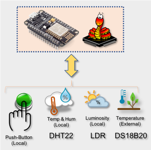
Here, the block diagram of our project:

Step 1: BoM - Bill of Material
- NodeMCU - US$ 8.39
- DHT22 Temperature and Relative Humidity Sensor - USD 9.95
- DS18B20 Waterproof Temperature Sensor - USD 5.95
- OLED Display SSD1366- USD 8.99 (optional)
- LDR (1x)
- LEDs (1x) (Optional)
- Push Button (1x)
- Resistor 4K7 ohm (2x)
- Resistor 10K ohm (1x)
- Resistor 220 ohm (1x)
Step 2: The Hw
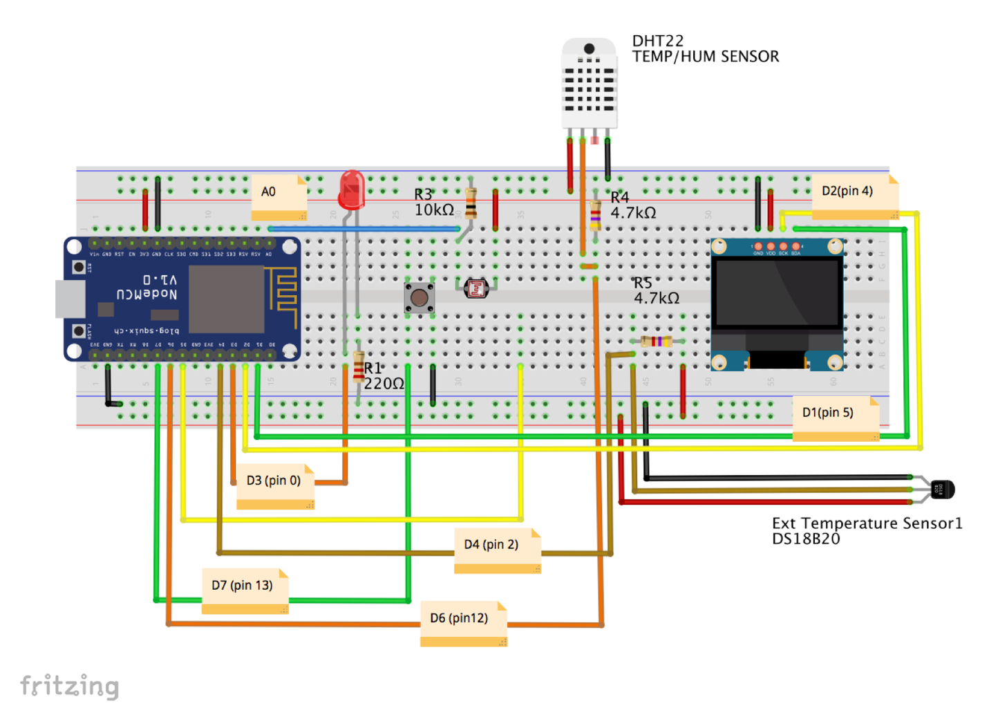
The Hw that we will use here basically is the same used on the tutorial: Micropython on ESP Using Jupyter. Refer to it for all HW connections.
The exception is the Servo, that we will not be used in this project.
Above you can see the full HW. Connect the devices as shown there.
Step 3: Micropython, REPL, Jupyter


You must have a Micropython interpreter loaded on your ESP device. Once loaded, you should program your ESP using any of available ways/IDEs available, like:
- REPL
- Jupyter Notebook
- Mu
- ESPCut (Windows only)
- ... etc
On my tutorial, Micropython on ESP Using Jupyter, I detailed how to download and install MicroPython interpreter, ESPTool to manage ESP devices and how to use Jupyter Notebook as a Development Environment. Feel free to use what is more comfortable for you.
I usually make all development on Jupyter Notebook, and once I get the final code, I copy them to Geany and load it on my ESP using Ampy.
Step 4: Sensors
Let's install the libraries, define GPIO, create objects, functions for all sensors individually:
A. DHT (Temperature and Humidity)
Let's Install the DHT library and create an object:from dht import DHT22 from machine import Pin dht22 = DHT22(Pin(12))
Now, create a function to read DHT sensor:
def readDht():
    dht22.measure()
    return dht22.temperature(), dht22.humidity()
Test DHT function: print (readDht())
The result should be for example:
(17.7, 43.4)
B. DS18B20 (External Temperature)
Let's Install the libraries and create an object:
import onewire, ds18x20
import time

# Define which pin the 1-wire device will be connected ==> pin 2 (D4)
dat = Pin(2)

# create the onewire object
ds = ds18x20.DS18X20(onewire.OneWire(dat))
Scan for devices on the bus
sensors = ds.scan()
print('found devices:', sensors)
The printed result is not really important, what we will need is the first detected sensor: sensors[0]. And now, we can build a function to read sensor data:
def readDs():
    ds.convert_temp()
    time.sleep_ms(750)
    return ds.read_temp(sensors[0])
It is always important to test the sensor using the created function
print(readDs())If you get a temperature value, your code is correct:
17.5
C. LDR (Luminosity)
The LDR will use the analog pin of our ESP (it is only one in the case of ESP8266 and several to ESP32).
Refer to my ESP32 tutorial for details.
Same as done before:
# import library
from machine import ADC

# Define object
adc = ADC(0)
A simple function: adc.read() can be used to read the ADC value. But remember that the internal ADC will convert voltages between 0 and 3.3V in correspondent digital values, varying from 0 to 1023. Once we are interested in "Luminosity", we will consider Max light as the maximum captured value from the sensor (in my case 900) and minimum light that in my case is 40. Having those values we can "map" the value from 40 to 900 in 0 to 100% of luminosity. For that, we will create a new function:
def readLdr():
    lumPerct = (adc.read()-40)*(10/86) # convert in percentage ("map")
    return round(lumPerct)
You should test the function using print (readLDR()). The result should be an integer between o and 100.
D. Push-Button (Digital Input)
Here we are using a Push-Button as a digital sensor, but it could be an "echo" of an actuator (A pump that was turned ON/OFF, for example).
# define pin 13 as an input and activate an internal Pull-up resistor:
button = Pin(13, Pin.IN, Pin.PULL_UP)

# Function to read button state:
def readBut():
        return button.value()
You can test the button reading the function print(readBut()). W/o pressing the result should be "1". Pressing the button, the result should be "0"
Step 5: Capturing and Displaying Locally All Sensor Data

Now that we have created one function for each sensor, let's create the last one that will read all of them at the same time:
def colectData():
    temp, hum, = readDht()
    extTemp = readDs()
    lum = readLdr()
    butSts = readBut()
    return temp, hum, extTemp, lum, butSts
Now if you use: print(colectData())
Will result in a tuple that includes all captured data from sensors:
(17.4, 45.2, 17.3125, 103, 1)
We can also optionally, show those data on a local display:
# import library and create object i2c
from machine import I2C
i2c = I2C(scl=Pin(5), sda=Pin(4))

# import library and create object oled
import ssd1306
i2c = I2C(scl=Pin(5), sda=Pin(4))
oled = ssd1306.SSD1306_I2C(128, 64, i2c, 0x3c)

# create a function:
def displayData(temp, hum, extTemp, lum, butSts):
    oled.fill(0)
    oled.text("Temp:    " + str(temp) + "oC", 0, 4)
    oled.text("Hum:     " + str(hum) + "%",0, 16)
    oled.text("ExtTemp: " + str(extTemp) + "oC", 0, 29)
    oled.text("Lumin:   " + str(lum) + "%", 0, 43)
    oled.text("Button:  " + str(butSts), 0, 57)
    oled.show()

# display data using the function
displayData(temp, hum, extTemp, lum, butSts)
As an option, I will also include the LED to be ON when we start reading sensors, going OFF after that data is displayed. Doing this will help to confirm that the program is working when we have the ESP disconnected from PC and running automatically.
So, the "main function would be:
# Main function to read all sensors
def main():
    # display data with a function
    led.on()
    temp, hum, extTemp, lum, butSts = colectData()
    displayData(temp, hum, extTemp, lum, butSts)
    led.off()
So, executing main(), we will get the sensor data displayed on OLED as shown in the picture.
Step 6: Running the Local Station Code on ESP Start-up

We can have all that was developed so far on a single file to be executed by our ESP.
Let's open any text editor and past on it all code:
# import general libraries
from machine import Pin
import time

# define pin 0 as output
led = Pin(0, Pin.OUT)

# DHT
from dht import DHT22
dht22 = DHT22(Pin(12))

# Function to read DHT
def readDht():
    dht22.measure()
    return dht22.temperature(), dht22.humidity()

# DS18B20
import onewire, ds18x20

# Define which pin the 1-wire device will be connected ==> pin 2 (D4)
dat = Pin(2)

# Create the onewire object
ds = ds18x20.DS18X20(onewire.OneWire(dat))

# scan for devices on the bus
sensors = ds.scan()

# function to read DS18B20
def readDs():
    ds.convert_temp()
    time.sleep_ms(750)
    return round(ds.read_temp(sensors[0]), 1)

# LDR
from machine import ADC

# Define object
adc = ADC(0)

#function to read luminosity
def readLdr():
    lumPerct = (adc.read()-40)*(10/86) # convert in percentage ("map")
    return round(lumPerct)

# define pin 13 as an input and activate an internal Pull-up resistor:
button = Pin(13, Pin.IN, Pin.PULL_UP)

# Function to read button state:
def readBut():
        return button.value()

# Function to read all data:
def colectData():
    temp, hum, = readDht()
    extTemp = readDs()
    lum = readLdr()
    butSts = readBut()
    return temp, hum, extTemp, lum, butSts

# import library and create object i2c
from machine import I2C
i2c = I2C(scl=Pin(5), sda=Pin(4))

# import library and create object oled
import ssd1306
i2c = I2C(scl=Pin(5), sda=Pin(4))
oled = ssd1306.SSD1306_I2C(128, 64, i2c, 0x3c)

# create a function:
def displayData(temp, hum, extTemp, lum, butSts):
    oled.fill(0)
    oled.text("Temp:    " + str(temp) + "oC", 0, 4)
    oled.text("Hum:     " + str(hum) + "%",0, 16)
    oled.text("ExtTemp: " + str(extTemp) + "oC", 0, 29)
    oled.text("Lumin:   " + str(lum) + "%", 0, 43)
    oled.text("Button:  " + str(butSts), 0, 57)
    oled.show()

# Main function to read all sensors
def main():
    # display data with a function
    led.on()
    temp, hum, extTemp, lum, butSts = colectData()
    displayData(temp, hum, extTemp, lum, butSts)
    led.off()


'''------ run main function --------'''
main()
Save it, for example as localData.py.
To run this code directly on your terminal you will need Ampy.
First, on Terminal let's inform Ampy our Serial port:
export AMPY_PORT=/dev/tty.SLAB_USBtoUART
Now, we can see the files that are inside our ESP root directory:
ampy ls
As a response, we will get boot.py, that is the first file that will run in the system.
Now, let's use Ampy to load our python Script LocalData.py as /main.py, so the script will run just after boot:
ampy put localData.py /main/py
If we use the command amp ls now, you will see 2 files inside the ESP.: boot.py and main.py
Resetting your ESP, will make the program localData.py run automatically, displaying the sensor data on display.
The above Terminal print screen shows what we have done.
With above code, the display will be shown only once, but we can define a loop on main() function, that will show data on every defined time interval (PUB_TIME_SEC), and for example, until we press the button:
# loop getting data until button is pressed
while button.value():
        led.on()
        temp, hum, extTemp, lum, butSts = colectData()
        displayData(temp, hum, extTemp, lum, butSts)
        led.off()
        time.sleep(PUB_TIME_SEC)
The variable PUB_TIME_SEC must be declared by the time that you want your samples.
To enhance more our code, would be good to inform that we will go out from the loop, for that we will define 2 new general functions, one for clear the display and another to blink the LED on a certain number of times.
# Clear display :
def displayClear():
    oled.fill(0)
    oled.show()

    # create a blink function
def blinkLed(num):
    for i in range(0, num):
        led.on()
        sleep(0.5)
        led.off()
        sleep(0.5)
So, we can now, rewrite our main() function:
while button.value():
        led.on()
        temp, hum, extTemp, lum, butSts = colectData()
        displayData(temp, hum, extTemp, lum, butSts)
        led.off()
        time.sleep(PUB_TIME_SEC)
blinkLed(3)
displayClear()
The final code can be downloaded from my GitHub: localData.py and also the Jupyter Notebook used for development of full code: Jupyter Local Data Development.
Step 7: Connecting the ESP to Local WiFi

The network module is used to configure the WiFi connection. There are two WiFi interfaces, one for the station (when the ESP8266 connects to a router) and one for the access point (for other devices to connect to the ESP8266). Here, our ESP will be connected to local network. Let's call the library and define our network credentials:
import network
WiFi_SSID = "YOUR SSID"
WiFi_PASS = "YOUR PASSWORD"
The function below can be used to connect the ESP to your local network:
def do_connect():
    wlan = network.WLAN(network.STA_IF)
    wlan.active(True)
    if not wlan.isconnected():
        print('connecting to network...')
        wlan.connect(WiFi_SSID, WiFi_SSID)
        while not wlan.isconnected():
            pass
    print('network config:', wlan.ifconfig())
Running the function, you can get as a result the IP address:
do_connect()
The result will be:
network config: ('10.0.1.2', '255.255.255.0', '10.0.1.1', '10.0.1.1')
Were, in my case, 10.0.1.2, is the ESP IP address.
Step 8: The ThingSpeak

At this point, we learned how to capture data from all sensors, displaying them on our OLED. Now, it is time to see how to send those data to an IoT platform, the ThingSpeak.
Let's begin!
First, you must have an account at ThinkSpeak.com. Next, follow the instructions to create a Channel and take note of your Channel ID and Write API Key.
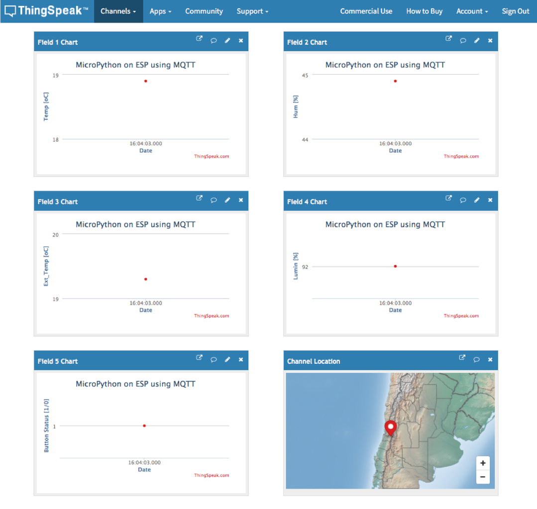
Above you can see the 5 fields that will be used on our Channel.
Step 9: MQTT Protocol and ThingSpeak Connection
MQTT is a publish/subscribe architecture that is developed primarily to connect bandwidth and power-constrained devices over wireless networks. It is a simple and lightweight protocol that runs over TCP/IP sockets or WebSockets. MQTT over WebSockets can be secured with SSL. The publish/subscribe architecture enables messages to be pushed to the client devices without the device needing to continuously poll the server.
The MQTT broker is the central point of communication, and it is in charge of dispatching all messages between the senders and the rightful receivers. A client is any device that connects to the broker and can publish or subscribe to topics to access the information. A topic contains the routing information for the broker. Each client that wants to send messages publishes them to a certain topic, and each client that wants to receive messages subscribes to a certain topic. The broker delivers all messages with the matching topic to the appropriate clients.
ThingSpeak™ has an MQTT broker at the URL mqtt.thingspeak.com and port 1883. The ThingSpeak broker supports both MQTT publish and MQTT subscribe.
In our case, we will use: MQTT Publish

The figure describes the topic structure. The Write API Key is required to publish. The broker acknowledges a correct CONNECTrequest with CONNACK.
The MQTT protocol is supported in a built-in library in the Micropython binaries -- this protocol can be used send data from your ESP8266, over WIFI, to a free cloud database.
Let's use the umqtt.simple library:
from umqtt.simple import MQTTClient
And knowing our SERVER ID, it is possible to create our MQTT client object:
SERVER = "mqtt.thingspeak.com"
client = MQTTClient("umqtt_client", SERVER)
Now, having your ThingSpeak credentials on hand:
CHANNEL_ID = "YOUR CHANNEL ID"
WRITE_API_KEY = "YOUR KEY HERE"
Let's create our MQTT "Topic":
topic = "channels/" + CHANNEL_ID + "/publish/" + WRITE_API_KEY
Let's get our data to be sent to ThingSpeak IoT Service, using the created function and associate its response to specific data variables:
temp, hum, extTemp, lum, butSts = colectData()
With those variables updated, we can create our "MQTT Payload":
payload = "field1="+str(temp)+"&field2="+str(hum)+"&field3="+str(extTemp)+"&field4="+str(lum)+"&field5="+str(butSts)
And that's it! We are ready to send data to ThinsSpeak, simply using the 3 lines of code below:
client.connect()
client.publish(topic, payload)
client.disconnect()
Now, if you go to your channel page (as mine above) you will see that each one of the 5 fields will have data related to your sensors.
Step 10: Sensor Data Logger

Now, that we know that with only a few lines of code it is possible to upload data to an IoT service, let's create a loop function to do it automatically at a regular interval of time (similar to what we have done with "Local data").
Using the same variable (PUB_TIME_SEC), declared before, a simple main function to continuously capture data, logging them on our channel would be:
while True:
    temp, hum, extTemp, lum, butSts = colectData()
    payload = "field1="+str(temp)+"&field2="+str(hum)+"&field3="+str(extTemp)+"&field4="+str(lum)+"&field5="+str(butSts)
    client.connect()
    client.publish(topic, payload)
    client.disconnect()
    time.sleep(PUB_TIME_SEC)
Note that only the "payload" must be updated, once "topic" is related to our channel credential and will not change.
Looking for your ThingSpeak channel page, you will observe that the data will be loading continuously to each field. You can cover the LDR, put your hand on temp/hum sensors, press the button, etc. and see how the channel will be automatically "log" those data for future analysis.
Usually, for Data Logging, we should try to use as less power as possible, so, we would not use the LED or display locally. Also, it is common with ESP devices, put them on "deep sleep", where the microprocessor will be on its state of minimum energy until it is time to capture data and send them to the IoT platform.
But, once here the idea is learning, let's also include the display and LED as we did before. Doing that, our "logger" function will be:
while button.value():
        led.on()
        temp, hum, extTemp, lum, butSts = colectData()
        displayData(temp, hum, extTemp, lum, butSts)
        led.off()

        temp, hum, extTemp, lum, butSts = colectData()
        payload = "field1="+str(temp)+"&field2="+str(hum)+"&field3="+str(extTemp)+"&field4="+str(lum)+"&field5="+str(butSts)
        client.connect()
        client.publish(topic, payload)
        client.disconnect()

        time.sleep(PUB_TIME_SEC)
blinkLed(3)
displayClear()
The complete microPython script can be found here: dataLoggerTS_EXT.py and the Jupyter notebook that was used for development can be also found here: IoT ThingSpeak Data Logger EXT.ipynb.
To upload the script on ESP, on your terminal use the command:
ampy put dataLoggerTS.py /main.py
And press the ESP - reset button. You will have the ESP capturing data and logging them on ThingSpeak.com until the bottom is kept pressed (wait for the LED to blink 3 times and the OLED turn off).
Step 11: The ThingView App

The data logged can be view directly on ThingSpeak.com site or via an APP, for example, ThingsView!
ThingView is an APP developed by CINETICA, that enables you to visualize your ThingSpeak channels in an easy way, just enter the channel ID and you are ready to go.
For public channels, the application will respect your windows settings: color, timescale, chart type and the number of results. The current version supports line and column charts, the spline charts are displayed as line charts.
For private channels, the data will be displayed using the default settings, as there is no way to read the private windows settings with the API key only.
Step 12: Conclusion

As always, I hope this project can help others find their way into the exciting world of electronics!
For details and final code, please visit my GitHub depository: IoT_TS_MQTT
For more projects, please visit my blog: MJRoBot.org
Saludos from the south of the world!
See you in my next instructable!
Thank you,
Marcelo


![Tim's Mechanical Spider Leg [LU9685-20CU]](https://content.instructables.com/FFB/5R4I/LVKZ6G6R/FFB5R4ILVKZ6G6R.png?auto=webp&crop=1.2%3A1&frame=1&width=306)


