

Introduction: IoT Outdoor Pet Door


I was inspired by this instructable to create an automatic chicken coop door. Not only did I want the chicken coop door on a timer, but I also wanted to connect the door to the internet so that I could control it with my phone or my computer. This door was built for my chicken coop, however, it could easily be applied to other types of housing for a variety of pets. You could also use different kinds of 12V motors besides the old car antenna motor I used.
After setting up and connecting Adafruit IO and IFTTT to my ESP8266, my chicken coop door can be controlled online. The door can be opened or closed:
1) At precise times that I enter on adafruit.io
2) By pushing a button on my phone
3) By sending a text message to a specific number
4) By clicking on a button on adafruit.io
5) By pushing a physical button
On top of those features, the chicken coop door can send push notifications to my phone through the IFTTT app about any problems with the door such as the door failing to open or close.
Because my chicken coop is outside about 500 ft away from my WiFi router, I used a 433MHz RFM69HCW transmitter and receiver paired with an ESP8266 to accomplish this project. There is an black indoor transmitter box with hardware that is connected to the internet and a gray outdoor receiver box that controls the motor.
This instructable will take you through the process of creating the hardware required to control a 12V motor that opens or closes my chicken coop door.
I used the following parts:
Adafruit 32u4 with 433MHz RFM69HCW - $25
Adafruit MCP23017 I2C 16 input/output port expander IC - $2.95
Adafruit Feather HUZZAH with ESP8266 WiFi - $16.95
Adafruit Radio FeatherWing 433MHz RFM69HCW - $10
Adafruit SMA Connector for 1.6 mm thick PCBs - $2.50
Adafruit uFL SMA Antenna Connector - $0.75
Adafruit RGB Push button - $10.95
12V power supply - $7
5V USB power supply - $7
Micro USB Cable - $5
4 Channel Relay Board (can use 2 channel)- $7
DC-DC Buck Converter (only used one but come as a pack of 5) - $20
Reed Switch (magnetic door switch sensor) - $9
2x 433MHz Omnidirectional Antenna - $6
uFL to SMA Cable Adapter (only used one but come as pack of 2) - $5
Waterproof outdoor ABS project box - $11
Black ABS project box - $10
20x4 Blue Character LCD - $10
12V Car Antenna Motor - ~$25 on ebay
Wire and resistors
Step 1: Outdoor Receiver


The outdoor receiver consists of an Adafruit 32u4 with 433MHz RFM69HCW connected to a few relays that switch on or off power for a 12V motor. These modules as well as a 12V to 5V DC-DC converter are inside of a waterproof gray project box. Finally, there is a door switch sensor connected to one of the pins of the 32u4 Arduino microcontroller that senses whether or not the door properly opened or closed when it should have.
Every 15 seconds, the indoor transmitter will send "Open" or "Close." Based off of the received command, the Arduino 32u4 will turn on or off a relay. For the motor that I chose, which is an old car antenna motor, I had to turn on or off two relays because of how the motor is wired. Basically there was a relay to turn on the power and then another relay that controlled whether or not the motor extended or retracted.
Once the open or close transmission is received, the outdoor receiver responds with "sensorOpen" or "sensorClosed" to indicate the status of the door switch sensor. Ideally, the "open" command would return a "sensorOpen" response, however, if the door gets stuck or the motor jams, these will not match. When they don't match, the indoor transmitter will display that information and a push notification will be sent to your phone.
Step 2: Connecting Outdoor Receiver Hardware


The hardware for the outdoor receiver is not too difficult to wire up. I included a fritzing schematic below so that the pins that I used can be easily viewed.
As I stated above, the motor I used required two relays. I included a picture of the pinout. The second you connect 12V to the red wire, the motor will retract if its extended. If you connect 12V to the red wire and the green wire at the same time, the motor will extend.
The reed switch I linked above should be wired as a a normally closed switch. The difference between normally open and normally closed is explained in the picture I attached above. Using software, there is an internal pullup resistor attached to the input pin on the 32u4, so all you need to do is connect the door switch to the input pin and also to ground.
You will have to attach an antenna to the Adafruit 32u4. Please check out Adafruit's really well explained tutorial on this step. I chose to use an external antenna instead of a piece of wire to get better range.
Attachments

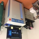
Step 3: Indoor Transmitter


The indoor transmitter consists of an Adafruit Radio FeatherWing 433MHz RFM69HCW stacked on top of an Adafruit Feather HUZZAH with ESP8266 WiFi. These modules are connected to a 20x4 character display and a RGB silver button inside of a black project box.
The display has a NTC synced clock, the RSSI strength in dB (measures strength of radio signals), the time when the chicken coop door will open, the time when the chicken coop door will close, and the current status of the door. The button is red when the door is closed and green when the door is open.
If the outdoor receiver looses power or if the 433MHz signal cannot be sent for whatever reason, the display and RGB button will go into the first of two possible error modes. In the first error mode, the display will say "ERROR! Try restarting the outdoor receiver." and the button will not have a color. If the door switch sensor detects the door did not properly close or open, the display and RGB button will go into the second of two error modes. In the second error mode, the display will say "ERROR! Door or switch sensor issue." and the button will not have a color. When the issue resolves itself, the display and RGB button will go back to normal. You can receive push notifications to your phone if either of these error modes occur (I'll go over that setup in a later step).
Step 4: Connecting Indoor Transmitter Hardware


After stacking the Adafruit Radio FeatherWing 433MHz RFM69HCW on top of an Adafruit Feather HUZZAH with ESP8266 WiFi, there are only 2 pins left that are not taken, the I2C pins SDA and SCL. This is why I went with the MCP23017 integrated circuit (IC). Its a really cool IC that connects up to 16 additional input/output pins to any microcontroller over I2C. Plus, there is a pre-written library called Adafruit-RGB-LCD-Shield that uses this IC with a character display that is technically written for this Adafruit product, however, it works perfectly for this project.
The idea to use the MCP23017 with a character display comes from this very well written instructable. Please check it out!
I took that instructable and instead of connecting multiple buttons and an RGB display to the IC, I only connected one button that had an RGB LED inside of it and a monochrome display to the IC. This allowed me to define PIN 1 of the IC (typically used for the blue backlight of an RGB display) as the backlight for my monochrome display, PIN 28 (typically used for the green backlight of an RGB display) as the red LED inside the button, and PIN 27 (typically used for the red backlight of an RGB display) as the green LED inside the button. PIN 24 was connected to one side of the button and the other side was connected to ground. You can see the pinout of the button in the picture attached above (I left the blue cathode disconnected).
Besides using that instructable I linked to help wire up the display, I have included a fritzing schematic that will help you connect everything.
You will have to short three pins on the top of the FeatherWing 433MHz RFM69HCW as explained by this Adafruit tutorial. You will also have to attach an antenna to the FeatherWing 433MHz RFM69HCW. Please check out Adafruit's really well explained tutorial on this step. I chose to use an external antenna with a side mounted SMA connector instead of a piece of wire to get better range.
Attachments
Step 5: Connecting to Adafruit.IO and IFTTT


Adafruit IO:
Please follow the instructions on this Adafruit tutorial to sign up for Adafruit.IO if you do not have an account. You should also read about what a feed and a dashboard is.
In simple terms, a dashboard is sort of like the graphical user interface while the feeds are what you send data to so that you can store it on the internet. You will need to create 1 Dashboard and 4 Feeds. I named mine before I knew how to spell chicken coop correctly, so please forgive the incorrect spelling. If you do not want to rename the feed names in the arduino code, just use the same naming I did.
Create the four feeds first:
1) "Chicken Coup" --> This is for the Open/Closed switch
2) "Chicken Coup Timer" --> This is for the open timer
3) "Chicken Coup Timer 2" --> This is for the close timer
4) "Chicken Coup Error Message" --> This is for the error messages
Create a dashboard next called Chicken Coup and add 4 blocks using the blue + button. Please see the picture above for the types of blocks you should place as well as the names of the blocks. Make sure to name the switch statuses exactly "Open" and "Closed"
IFTTT:
The IFTTT part of this project adds the capability to push a button on your phone and send a text to open or close the chicken coop door. It also allows the IFTTT app to send you push notifications if anything is published to the Chicken Coup Error Message feed. If you do not want these capabilities, you may skip this section.
First, set up a IFTTT account if you do not already have one. If you want to use the pre-made applets that I created, just navigate to my account and turn on the applets that you want. Otherwise, you will have to create your own, and subscribe or publish to the adafruit feed you created above.
Step 6: Uploading Code & Editing WiFi SSID and Password
You will need to go through this page of the Adafruit tutorial to be able to upload code to the indoor transmitter.
You will need to go through this page of the Adafruit tutorial to be able to upload code to the outdoor receiver.
You will need to install the RFM69 library, the Adafruit_RGBLCDShield library, the NTC clock library called simpleDSTadjust, and the ticker library. You can find a tutorial on how to do that here.
Open Arduino IDE and the upload the "Outdoor_Receiver.ino" code to the outdoor Arduino 32u4 over a USB cable.
Then, open "Indoor_Transmitter.ino", open the config.h tab, and enter in your WiFi name (SSID) and password inside of the quotation marks. Then, obtain your Adafruit.IO username and IO Key by following this tutorial page and enter it into the config.h tab.
If you changed the names of the Adafruit IO feeds, you will need to edit the code in the Indoor_Transmitter main tab. Edit the following:
AdafruitIO_Feed *toggleSwitch = io.feed("Chicken Coup");
AdafruitIO_Feed *timer = io.feed("Chicken Coup Timer");
AdafruitIO_Feed *timer2 = io.feed("Chicken Coup Timer 2");
AdafruitIO_Feed *error = io.feed("Chicken Coup Error Message");
That should be all that you have to do! If you would like to further understand how the two sketches works, I commented the code. Please let me know if you have any questions. Good luck!

![Tim's Mechanical Spider Leg [LU9685-20CU]](https://content.instructables.com/FFB/5R4I/LVKZ6G6R/FFB5R4ILVKZ6G6R.png?auto=webp&crop=1.2%3A1&frame=1&width=306)


