

Introduction: Jammafying Turbo Outrun


In this instruction set I will explain how to make a JAMMA harness to Turbo Outrun. Turbo Outrun is based on the Outrun hardware, with different rom set.
Stuff you will need for the process:
- Turbo Outrun Board
- 56 pin finger board
- DuPont male and female connectors with housing
- Basic soldering skills
- Soldering iron with some soldering skills
- DuPont crimping tool
- 24-26 AWG wire
- Wheel and pedals that uses potentiometers - I got mine second hand
- Outrun owners manual
- Arcade PSU
- Standard consumer supergun that uses neo-geo controller port pinouts
- JAMMA pinout diagram
- Patients and a lot of it ;)
The idea is to use a standard Supergun for the game with custom wheel and pedals controls for it. The wheel and pedals details will not be discussed in this article.
Make sure you know how to handle sensitive electronic PCB.
Step 1: I/O


Board i/o ports:
- Power plugs - The power plugs are 10 pins each divided into 2 rows. The game runs on +5v and ground.
- 50 pin plug (AMP50) - supports several functions such as coin and start button
- 20 pin plug (AMP20) - supports controls such as wheel and pedals.
- Sound plug - in my sound cable, there are 3 channels, marked by the colors: Red, Blue and White. I looked inside the out run owners manual but there it has only 2 channels (left and right). I went with Red for right and White for left
- Video plug - red, green, blue and sync
I got the original wire harness for the board, but you can replace the Power Plugs, 50 pin and 20 pin plugs with the Dupont connectors. For the Sound and Video you'll need a Molex type connector to hook to the PCB.
Step 2: The Conversion


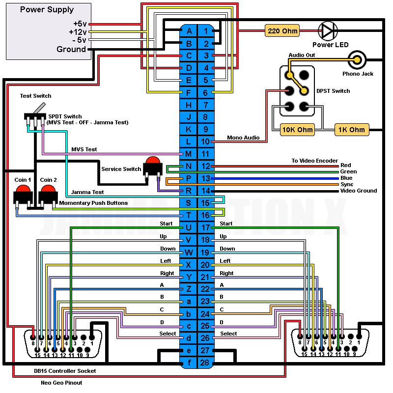
In order to set the controls, first let's look at a Jamma wiring diagram. the general idea is to use a standard SuperGun to run the game, so we'll need to wire the controls to the Supergun's controller port.
standard Jamma controls per player consist of 4 directions, and 4 push buttons, a start and select (for mvs boards).
the controls in our case will consist of a Wheel, two pedals, Turbo button, and the standard Start button (coin and service switches are being handled by the supergun itself).
A potentiometer based control uses 3 wires: +5v, pot and GND.
We shared GND and +5v for the Wheel and 2 pedals, so what is left to do is route the pot per control component.
shared GND will be connected to pin 1 on the controller port and shared +5v will be connected to pin 8 on the controller port.
Follow the tables for AMP50 and AMP20 pinouts to JAMMA finger board. You also got a main table that summarize the JAMMA and DB15 routing.
Step 3: Conclusion

- Make sure your using an arcade PSU, some of the older boards will require higher voltage to function correctly.
- As you're sharing the +5v and GND for the wheel and pedals POTs, make sure you're connecting them in PARALLEL and not SERIAL.
- Use 5Kohm POTs for the job, they are what sega used and so the calibration will be much easier.
If you like it, be sure to check my Facbook page Arcade Board Players for more projects.
Feel free to comment and ask questions if something is not clear. I would be happy to update if necessary.
Thank you


![Tim's Mechanical Spider Leg [LU9685-20CU]](https://content.instructables.com/FFB/5R4I/LVKZ6G6R/FFB5R4ILVKZ6G6R.png?auto=webp&crop=1.2%3A1&frame=1&width=306)


