

Introduction: Knot: a Robotic Offcut of Scrap Lumber


Recently, I made a firewood holder in my backyard. It was a very simple design, made purely from 2x4 lumber, making it quite cheap and easy to build. But this Instructable is not about that project. After finishing my firewood holder, I had a couple leftover offcuts of lumber, as is common with just about any construction project. And, instead of letting those pieces sit in the Useful Offcuts of Wood section of the shop, I decided I should find a way to put those pieces to good use. Since I was also looking for ways to use the trim router I just bought, the project in which I could use this excess lumber was obvious: I would build a robot from spare pieces of framing lumber. I named the robot, Knot.

The robot we will build in this Instructable is quite simple. Using a router, we will mostly hollow out a spare piece of 2x4 lumber. The cavities we will create will hold a stepper motor on each side of the board, and a little collection of electronic bits in the middle.
The motors are used to turn two small pieces of wood on the ends of the board, allowing the robot to move forward, backward, or turn in place.
The robot uses a novel approach to control. Gone are any radio transmitters or Bluetooth apps; we will use a wooden mallet (the kind used to play the glockenspiel) for control by knocking on the top of the robot:
- A single knock moves the robot forward.
- Two knocks turns the robot right.
- Three knocks turns the robot left.
- Four knocks moves the robot backward.
Inside the robot, we will use a couple of SparkFun's Qwiic products for running the robot's firmware and controlling the motors.

Let's get started.
Supplies
Here's everything you will need to make your very own robotic 2x4 offcut:
- A piece of 2x4
The main chassis for the Knot robot will be made from whatever random offcut of 2x4 lumber you happen to have sitting around. It just needs to be at least 450mm long.
- 2x NEMA 11 Stepper Motor
The power to animate a random piece of wood comes from two of the most adorable little stepper motors you've probably ever seen. These NEMA 11 bipolar stepper motors, one for each side of the wood, measure just 28mm square. They will rotate small pieces of wood at the ends of the main wooden robot chassis and propel Knot into the wider world.
https://www.omc-stepperonline.com/nema-11-bipolar-1-8deg-12ncm-17oz-in-0-67a-6-2v-28x28x51mm-4-wires.html - SparkFun RedBoard Artemis
The "brain" inside the Knot robot - and it is actually quite a formidable brain - is the SparkFun RedBoard Artemis. This board is based on the Arduino Uno but its feature set goes far, far, far beyond that of the classic blue microcontroller. The Artemis module on this board incorporates a powerful microcontroller and Bluetooth connectivity. While we will not use Bluetooth in this Instructable, I thought it would be fun to include the ability to add some kind of controller in the future.
https://www.sparkfun.com/products/15444 - 2x SparkFun Qwiic Step Stepper Motor Driver
While the RedBoard Artemis is the brains of the robot, it does not directly control the two stepper motors. For that, we will use a pair of SparkFun's Qwiic Step stepper motor drivers.
https://www.sparkfun.com/products/15951 - Piezo Element
The Knot robot is controlled by knocking on the top of the wood with a mallet. We will use a basic piezo element to detect these knocks.
https://www.sparkfun.com/products/10293 - 100mm Qwiic Cable
This cable is used to connect the two stepper drivers together. That's about it.
https://www.sparkfun.com/products/14427 - Wooden Mallets
The robot will be controlled by knocking on its top with wooden mallets, the kind used to play the bells.
https://www.amazon.com/gp/product/B07SWYBTPG - Tapping Inserts for Wood
https://www.mcmaster.com/95631A050/
This cool parts are threaded inserts with an extra sharp thread on the outside as well. These can be screwed into holes in the wood to enable M3 screws to attach other parts. This technique will be better than screwing directly into the wood because it will allow us to use nylon screws (below) for attaching the electrical parts. - Nylon M3 x 6mm Screw
https://www.mcmaster.com/92492A716-92492A116/
We will use these screws to attach the electronics boards to the robot chassis. They are soft and nonconductive, making them perfect for attaching PCBs. - Nylon M3 Washer
https://www.mcmaster.com/95610A530-95610A330/
We will place these between the PCBs and the threaded inserts to insulate the boards from any potential shorts. - Generic 12V 2A Power Supply
Knot will be powered off a 12V 2A power supply. There are many generic power supplies that will fit the bill.
https://www.amazon.com/NorthPada-Portable-Turntable-Elliptical-Exercise/dp/B06XXQ1D71


Step 1: Cut the Board Into Sections


Alrighty, let's get stated with the build. The first step is to cut the spare piece of 2x4 lumber into three sections: the left and right "feet" for the robot, and the central chassis. These sections will be measured out in millimeters. The left and right feet are 50mm long, and the central chassis is 350mm long. I created a diagram to show these dimensions:

Square your Saw
Before we start cutting, it is a good idea to make certain your saw is square. Because the robot's feet have to rotate, we want to ensure the cuts are totally perpendicular to the sides of the board, or else the feet will rub into the body. There are several methods for squaring up your saw. I just a small machinist's square to ensure that the blade is perpendicular to the table.

Cut the Parts
We want the three parts to look seamless when the robot is viewed from the top, so we will cut the parts in sequence.
- Start by measuring 50mm from the outside edge of your board and cut off this first foot.
- Then, from the new end of the board, measure 350mm and cut off the main chassis.
- Finally, measure 50mm again from the end of the board, and cut off this last foot.


Step 2: Carve the Internal Cavities


Prepare to make a whole bunch of sawdust.
Now that we have the three sections of the robot cut to length, the next step will be using a router to create the cavities inside the main chassis piece (the longest one) that will hold the motors and electronics.
Measure and Mark the Design
The first step here will again be measuring the cuts. The measurements are a little bit more complex than before but I again created a diagram to show the dimensions:

So, you will basically need to measure out the different sections from the cutting pattern and copy them onto the board. I like to use a marker to color in the sections that will be removed. When you start cutting with the router, visibility will be quite limited and sawdust will be flying all over the place so it is best to make the cutting pattern as obvious as possible.

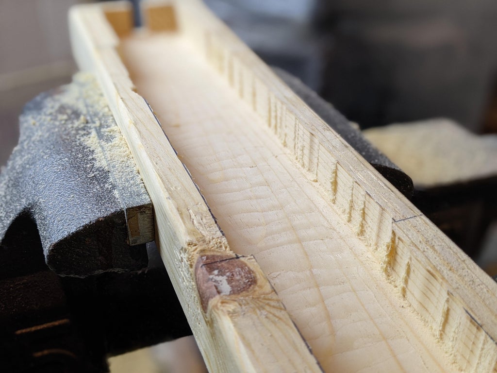
Cut the Cavity to 20mm Depth
There are three main cavities we will be cutting out with a router: one on each side for the motors and a central one for the electronics. Because the motors are a fair bit thicker than the electronics PCBs, their cavities will be deeper and the one for the electronics. So, the strategy we will use will be to first cut out the entire area of the three cavities to a depth of 20mm. This is the finished depth for the electronics section. Then, we will cut the motor cavities deeper.
So, start by inserting a straight bit into your router and setting the depth to 20mm.

When it comes to cutting out the design, I find it easiest to first cut the outlines of the shapes and then go back and hollow out the cavities.

The router is a great tool in general, but one of the things it excels at doing is generating sawdust. The sawdust will tend to collect in the cavities you are cutting and it will eventually start to interfere with the router. So, while you are cutting out the cavities, make sure to stop and clear out the sawdust whenever it gets too thick. You can turn the wood over and bang it into the table or something, but by the end, the wood will get very thin and fragile. So, I took an old paint brush and used it to sweep out the sawdust.

Once you get all the outlines cut, the rest is a matter of going back and forth with the router to clear out the interior of the cavities.
One thing to watch out for as you get close to removing all the material on the inside of the cavities is that you may get a little chunk of wood that breaks off at the end. It will then have a tendency to get kicked around under the router. If this happens, just switch the router off and remove the little piece before you continue cutting.
Cut the 35mm Depth Motor Cavities
Now that we have the entire cavity cut to a depth of 20mm, we will go back and deepen the motor cavities on the sides of the board to 35mm. So, to start, set the depth of the bit on the router to 35mm.

Next, we will need to re-draw the lines that divide the motor cavities from the electronics cavity since they got cut off by the router on the first pass.

Then, use the same technique as before to cut the motor cavities on the ends of the board down to a depth of 35mm. Now, this time, when removing the material from the inside of the cavity after going around the outside edge, be extremely careful and go slow. We are cutting almost the hole thickness of the board so the thin spot that remains is very fragile. If the router grabs the wood too hard, it can easy break through the bottom of the board (that will actually be the top of the robot). When you are done, you will end up with two levels of cavities inside the board.

Step 3: Drill Holes for the Motor Shafts


At this point, we can put down the router and pick up a drill instead. The next step is to drill holes in the feet parts to accept the motor shafts.
Mark Locations for the Holes
The first step in this process is to mark the locations for the holes. Because there is very little guarantee that the notches in the sides of the main chassis are centered (and they don't need to be anyway), we will mark locations for the holes empirically. First of all, match up the feet parts with the main chassis so you know which side of the feet are the interior sides.

Then, from the inside of the motor cavity, draw a line on the foot parts that shows where the opening in the main chassis sits.

We will drill a hole for the motor shaft on this line in the vertical center of the piece of wood.

Drill the Hole
Drilling the hole is quite easy. The motor shafts are 5mm in diameter, so we will use a 5mm drill bit to make the holes. In order to avoid going too deep, I placed a small piece of tape on the drill bit.

Then, simply drill a hole into each foot for the motors.

Step 4: Drill a Hole for the Power Cord


As long as you already have the drill warmed up, we can go ahead and drill one more hole, this time for the cord that supplies power to the robot. The hole will be in the center of the board length-wise and 10mm from the bottom side of the board (the side with the cavities hollowed out). This will put the hole in the exact center of the electronics cavity.
As usual, start by measuring out the location of the hole.

Then, using the same 5mm bit we used in the previous step, drill a hole through the side of the chassis and into the interior of the electronics cavity.

Step 5: Mount the Motors and Feet


Now we are done with the wood-cutting part of this Instructable so we will move on to installing the motors. Because the area of wood between the top of the robot and the motor chassis is so thin, we will not be able to use mechanical fasteners to attach the motors. Instead we will use glue. Specifically, we need a polyurethane-based glue to make the connection between the wooden parts and the metal motor. Original Gorilla Glue fits the bill.
Glue the Motors to the Chassis
So, first of all, let's figure out the orientation of the motors. For the sake of cable management, we will install the motors with their wires facing away from the side of the chassis with the hole for the power cable. With the first motor oriented in this way, place a small bead of glue on the side of the motor.

Then, wet the inside of the motor cavity with a little water. This helps the glue expand and set.

Place the motor into the cavity with the motor shaft sticking out of the gap in the end of the chassis. To hold the motor in place while we position the foot, loosely apply a clamp to hold the motor down. We will still need to move the motor a bit to get the foot alignment right, so don't fully tighten the clamp yet.
Repeat this procedure with the other motor.
Glue on the Feet
Next, stick some water inside the drill hole in the foot and then put a dollop of Gorilla Glue over the hole.

Then, being careful not to let the glue get between the foot and the chassis, put the chassis in place on the motor shaft. Hold the foot in place using a clamp placed on the end of the foot and the back of the motor. This clamp does not need to be super tight, just snug enough to prevent the foot from wandering out of position while the glue dries.

Then, as before, repeat this procedure with the other foot.

Step 6: Upload Firmware to the RedBoard Artemis


To make life a little easier, we will upload code to the RedBoard Artemis before installing it into Knot's chassis because, after the board is in place, it will be a tad challenging to access the USB-C port. So, the first step in the process of programming the RedBoard Artemis is to set up the Arduino IDE to be able to upload code to the board.
Install Artemis Board in Arduino IDE
Setting up the RedBoard Artemis in the Arduino IDE is quite easy and is well documented by SparkFun. This section is essentially a TL;DR version of their article.
- Add an additional board manager URL
The first step is to add an additional URL that the Arduino IDE will use when searching for boards in the Boards Manager. Start by navigating to File > Preferences.
Then, in the Additional Boards Manager URLs field, paste:<a href="https://raw.githubusercontent.com/sparkfun/Arduino_Boards/master/IDE_Board_Manager/package_sparkfun_index.json">https://raw.githubusercontent.com/sparkfun/Arduino...</a> - Install the SparkFun Apollo3 Board Package
Next we need to install the profile that will allow the Arduino IDE to upload code to the Apollo3 chip on the Artemis module onboard the RedBoard. Start by going to Tools > Boards > Boards Manager.
Then, search for Apollo3 and you should find an entry for the SparkFun Apollo3 Boards profile. Click the Install button to install the profile.


Upload the Knot Firmware
Now that the Arduino IDE is set up to upload code to the RedBoard Artemis, we can install the code that will run the Knot robotic piece of lumber. First of all, you can download the robot's firmware from GitHub:
https://github.com/Toglefritz/Knot
Once you've downloaded the sketch, open it in the Arduino IDE.
Before uploading the code to the RedBoard Artemis, you will need to select this board in the Arduino IDE. To do so, navigate to Tools > Board > SparkFun Apollo3 and select SparkFun RedBoard Artemis.

In the Tools > Port menu, select the COM port to which your board is connected.
Then, finally, click the Upload button.
How does it work?
For a detailed blow-by-blow of how the code works, check out the code itself because there are a bunch of comments in there. Here we can cover a high level summary.
The code is fairly simple. Basically all the action, aside from doing a couple things like initializing the motor controllers, happens in the loop. First, Each time through the loop, the sketch starts by taking a reading from the analog pin to which the piezo sensor is connected. The sketch is configured with a threshold value that determines the minimum sensor reading that will be considered a knock. So, after doing the analogRead from the piezo sensor, the sketch compares the reading to this threshold. If the reading is above the threshold, we have ourselves a knock!
The sketch needs to keep a count of the number of knocks to determine how the robot should move. So, when a knock is detected, the sketch adds one to the knock count, as well as records the time, in terms of millis(), that the knock occurred. Another configuration option in the sketch is the length of the time window during which the robot will accept additional knocks. If the loop reads another knock, based on the analogRead value, it will increment the knock count again. If the most recent knock occurred more than a certain length of time in the past, the sketch will stop counting knocks and move on to the fun part, moving the robot.
Based on the knock count, the sketch will move the motors in a way that makes the robot move. Turing both motors in the same direction moves the robot forward. Turing them in opposite directions makes the robot turn. It is a bit like driving one of those zero turn radius mowers.
After moving, the sketch resets the knock count and the process starts over with the next loop.
Step 7: Mount the Electronics Into the Chassis


Now that we have the firmware uploaded onto the RedBoard, we will get to work installing the electronics inside the Knot chassis. We had to mount the motors using glue because the wood underneath the motor cavities is very thin. However, the wood under the electronics cavity is much thicker, allowing us to use the more elegant solution, threaded inserts and screws, to attach the electronics.
Wire the Boards Together
Since the Quiic cables we have are limited in length - the longest is only 100mm long - we will wire the boards together so that we can ensure we do not accidentally mount the boards too far apart inside the robot's chassis for the cables to reach. First, using one of the short Quiic cables that came with the Quiic stepper motor drivers, connect the RedBoard to one of the stepper drivers. The Quiic stepper driver should be oriented with the terminal for the motor facing away from the RedBoard, so that it ends up closest to the motor after it is mounted in the chassis. There are two Quiic ports on the stepper drivers, it does not matter which one you connect to the RedBoard.

Then, using one of the 100mm Quiic cables, connect the two Quiic Step motor drivers together. Again, it does not matter which plug you use on the other stepper driver.

Mark Hole Locations
Next up, we need to mark the locations where we will drill holes for the threaded inserts. This is fairly easy to do. Place the electronics into the central part of the chassis. Then, being sure to leave space between the power connectors on the stepper drivers and the side of the cavity, use a pen to draw a dot on the wood for each hole.

Install the Inserts
Now that we know where to drill the holes, we can actually drill them. We will want to make certain that we do not drill the holes too deep. It would be a big problem if we accidentally punch through the top of the robot. So, we will use a similar technique to the one we used for drilling the holes for the motor shafts. Place a small bit of tape on a 6mm drill bit so that the protruding part of the bit is the length of the insert.

Drill holes at each of the marked locations. The holes should be as close to vertical as possible so that the inserts go in straight. Then, switch over to a flat bit in your drill for installing the inserts. Using plenty of pressure on the inserts, slowly screw them into the wooden chassis until the top of each insert is flush with the wood.
Glue in the Piezo Sensor
The first electronic part we will install will actually not involve all those threaded inserts we just put in place. Rather, because it goes underneath the RedBoard, we will start by gluing the piezo sensor into place. First, place a small dot of cyanoacrylate glue onto the brass side of the piezo sensor.

Then, glue the piezo sensor to near the side of the electronics cavity. We will end up connecting it ot pin A0 on the RedBoard, so make sure the leads protrude from that side of the microcontroller board. Apply pressure to the piezo sensor for 30 seconds to allow the glue to set.

Attach the Electronics
The final phase of this step is to finally attach the Redboard and the two stepper drivers to Knot's chassis. This is also quite an easy step. Start by placing the wired-together boards into the chassis the way you had them while marking the locations of their mounting holes. Then, for each mounting hole, slide a washer between the threaded insert and the PCB, followed by an M3 x 6mm screw.


Step 8: Wire the Motors and Piezo Sensor


So, now that all of the electronic components are mounted together inside the robot - and some of them even wired together already - the next step is to connect the stepper motors to the Quiic stepper drivers and the piezo sensor to the RedBoard. The ordering of the wires is important for connecting the motors to the drivers. So, the first task to accomplish is identifying the pairs of wires that form coils inside the stepper motors.
Identify Stepper Motor Coils
The NEMA 11 stepper motors we are using for this project are bipolar stepper motors, meaning there are two sets of electromagnetic coils that turn the motor shaft. Each coil is powered through two wires. So that is why each of our motors has four wires in total.

If you take a look at the motor connectors on the Quiic stepper drivers boards, you will notice they are labeled A+, A-, B+, B-. The A and B indicate the two coils inside the motor. So, we need to identify which pairs of wires are on the A coil on which are on the B coil.

We can figure out this pairing easily using a multimeter. The wires that are part of the same cable are electrically connected, whereas two wires on different coils are electrically isolated from each other. Therefore, to figure out the wire pairing, we will use the continuity test mode on the multimeter to identify which wires are connected to each other.

Connect the Stepper Motors to the Stepper Drivers
The stepper motors wires are obviously way, way too long for reaching the stepper driver boards. Therefore, the first step is to cut the wires until they are are just a little longer than the spaces between the motors and their neighboring drivers. Then strip the ends of the wires.
Then, using your knowledge about which wire pairs are on the same coil, connect the wires to the four-pin connectors on the stepper drivers. To make the connections, lift up the levers on the connectors, insert the wires, and press the levers back down.

Step 9: Wire in the Power


The next part of the electronics assembly to do list is the power supply cable. We will need to create a power input that distributes power to three parts of Knot's electronics stack: the RedBoard and each of the two Quiic stepper drivers boards. The power input itself will be provided by a barrel jack connector that extends outside the robot's chassis via the hole we drilled in the side earlier.
Create the Power Supply Wiring Harness
So, we will begin by creating a wiring harness that connects the barrel jack to three pairs of wires that will, in turn, connect to the three components we just mentioned. Start buy cutting three 150mm lengths of the red/black wire.

Then, strip the ends of all the wires.

We are going to connect one end of these wires to the barrel jack connector such that each wire pair acts to distribute the power in parallel. Therefore, on one end of the wire bundle, twist all of the black wires together and do the same for the red wires.

Finally, place the black and red twisted wire triplets in the barrel jack adapter, using the black wires as ground (negative) and red wires as positive. To help prevent the wires from separating and pulling out of the barrel jack connector, place a zip tie around the entire bundle of wires close to the barrel jack adapter.

Connect Power to the Electrical Components
Now that we've constructed the wiring harness, we can wire up power to the RedBoard and stepper drivers inside the robot. The first task though is getting the wires inside the harness. Do this by simply threading the bundle of power connectors through the hole we made before in the side of the piece of lumber.

Let's tackle the most difficult connection first, the connection to the RedBoard. The first step is to crimp male header pins into one of the black wires and one of the red wires so they can be connected to the female headers on the RedBoard, just like we did with the wires from the piezo sensor. So, using your crimping tool, attach these male pins to one wire of each polarity.

Then, the red (+) wire will plug into the VIN pin on the RedBoard, which is between the pins to which the Piezo sensor is connected. Like we did with the other connections to the RedBoard, bend this VIN pin down so that it is parallel to the board and does not stick out from the bottom of the robot.

Next we will attach the black ground wire to one of the GND pins on the RedBoard. There is one on the opposite side of the board from the VIN pin. Again, bend the header pin down so it does not protrude out of the robot's chassis.

Connect Power the Quiic Stepper Drivers
Now we can move on to connecting power to the two stepper drivers, which is an easier task. On each of the stepper driver boards, there is a header with lever locks and the labels "PWR" and "GND." So, it does not particularly matter which pin you connect first, but to connect the power wires, open the header by pulling up the white lever, insert the wire into the appropriate side, and push the lever back down.

Connect the black wire to GND and the red wire to PWR. Then, repeat this process for the other stepper driver.

Step 10: Play With Your New Robot Friend


Congratulations 🤖
Well would you look at that, we built a robotic piece of random, leftover lumber.

First Prize in the
Robots Contest


