

Introduction: Laser Cut Star Trek Enterprise Model


This is a project I did during my stay at Instructables as Artist in Residence, July 2013. It is part of my ongoing laser cut advent calendar project. That project should end up in a set of 25 little construction sets, for toys and gadgets, cut from one acrylic sheet.
As I am a Trekkie something Star Trek was bound to be included. And as for me the original Enterprise is still the ultimate icon of Star Trek. In this Instructables I explain how I made the design and how the model it is assembled
I’ve had a busy year and I’ve been neglecting writing up Instructables on a number of projects from that time. But as you see tomorrow (or next year in this case) does come!
The design is included in Step 3.
Step 1: Materials and Tools Needed:


The design is for 3mm thick acrylic sheet. You’ll need a piece of about 10 by 17 cm.
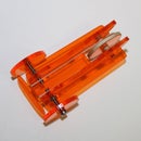
I used both white (for a more or less authentic result) and transparent orange (the theme colour of the advent calendar project – orange being THE Instructables colour AND my favourite colour)
You can use other sheet material that can be laser cut (like wood) and you can scale the design according to the thickness of your sheet. Making the display stand in a different material, like clear acrylic gives a nice result.
Obviously you’ll need access to a laser cutter, but of course you can use an online service.
I used a 120W Epilog laser cutter in the Instruictables workshop at Pier 9, but I also repeated it on the 25 Watt LaserPro Spirit. at timelab http://www.timelab.org/en in Ghent, Belgium.
On the 120W Epilog laser cutter, I cut with the speed set to 50% and the power 70%.
On the 25 Watt LaserPro Spirit I cut with the speed set to 0.8% and the power 100%.
Both laser cutters get their files straight from CorelDRAW running on a Windows computer. To make the design I used Inkscape (a free vector graphics editor available on all common platforms).
Step 2: Design Part 1


I went looking for a set of orthographic views on the web. I found a nice one here and imported it in a scaled vector graphic file in Inkscape.
I started drawing over the outlines to make the main parts. I tried to keep the model simple, with a low parts count. I first kept to the size the picture happened to come in, but later I scaled it up slightly so the resulting model is at a scale 1/2000 (about 15cm long) The saucer (primary hull in the orthographic view picture), the main strut and the nacelles (propulsion unit) with struts are obvious parts. The trick was to integrate the secondary hull as three parts coming together. Keeping these parts in the right angle was a mission I first reserved for the deflector dish (main sensor in the picture), but that didn’t look right so that became a ring behind the deflector dish.
Then I made the cut outs that allow to puzzle the parts together, taking in account a laser cut with of 0.2 mm
As in the other advent calendar projects, I tried to make the design tolerant for the typical thickness variations. On common acrylic sheet these can go up to + or – 15% of the nominal thickness. On this scale and with a brittle material like acrylic sheet, working with notches to take up the thickness variations. I made all slots a little wide and make tight fits only where cut edges touch cut edges. That is where the ring on the front of the secondary hull, behind the deflector dish comes in to hold the parts together. The deflector dish has a square hole that allows for a maximum sheet thickness, but the antenna on the main strut piece is cut to be tight fit to that.
An important correction to make is the nacelle strut length. In the orthographic view the projection of the angled struts makes them appear shorter. The correct length is taken from the front view and the the nodes drawing the nacelles are moved to lengthen the struts accordingly.
The height of the nacelles and secondary hull themselves are not corrected, as these have fairly circular sections, so the projection angle has little to no influence. I did correct the secondary hull bottom slightly to allow the model to stand.
For the saucer section some tension is needed to keep it in place, so I made a “spring” at the front of the main strut. It’s rather fragile, but it works and hardly shows when assembled.
Step 3: Design Part 2


For the display stand bottom I went for the shape of the Starfleet insigne. Again I started from an image I found, this time here.
I made long “springs” to hold the vertical part, that proved to be quite robust.
When test building I learned the thickness variations did give problems in some case. Actually the assembly of the Enterprise itself is fairly tolerant to thickness variations, up to the point of adding the display stand. In some case filing off some of the thickness at its top or add a drop of glue.
The Design is saved as a pdf (with the standard pdf 1.5 settings in Inkscape) to be able to import it in CorelDRAW running on the computer the laser cutters are connected to. To my experience pdf works best to transfer between Inkscape and CorelDRAW
The design included below. You can also find the design on Thingiverse as thing 470661.


Step 4: Assembly Phase 1


Carefully take the parts out of the sheet and remove all protective layers.
Start by putting together the two nacelle-strut-hull parts, at a right angle. Then add the main strut and fiddle the three parts in their corresponding position to fit on the front secondary hull ring. Add the deflector dish to help keep things in place
Step 5: Assembly Phase 2: Display Stand and Saucer


Next addthe vertical part of the display stand. This is the trickiest part. If it is too tight, it is better to file of some of the thickness, instead of risking to break the secondary hull parts. If it is to loose, a drop of glue can help keep it in place. You do not need to put the model perfectly straight on its stand. Some inclination can actually make for a better presentation.
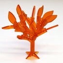
Add the display foot by sliding the vertical part between the springy shapes, starting from one side.
To add the saucer section, first slide it over the main strut, under the front notch. Then carefully slide the back end of the slit in place.
Ready!


