

Introduction: Laser Cut Zoetrope


This instructable shows how to make a hand cranked zoetrope using laser cut parts. The bevel gear is created by laminating layers of 1.5mm plywood cut to form a gear with a mitred profile.
I run Little Sandbox, a kids tech club and maker space, with Helen, Soosie and Snoofers. One of the most popular activities in our homeschool group is animation, the kids love telling stories with stop motion. Sometimes we like to get away from the screens, get the pens out and make flip books and thaumatropes. I wanted to make a zoetrope with our laser cutter that we could use in club. The design is based on the 1860's William Ensign Lincoln design, with viewing slits above an interchangeable strip of images.
Zoetrope animations are short, this example has sixteen frames, so at 24 frames per second that is two thirds of a second. There's not really time to follow a narrative arc in these films, but for short repeating movements they work really well. A historical example of the type of motion that works well is the study by Eadweard Muybridge of a horse's gait. Snoofers created the animation shown here, they have written a section of this instructable describing how to create your own animation strips.
Animations play fairly smoothly, although it has a stroboscopic effect so care should be taken if this causes medical problems. This is also true of the example video in this instructable.
None of the steps in assembly are particularly difficult but there are a lot of components and some are similar. I've tried to include plenty of photographs to show the steps. Unless you are particularly dexterous with tweezers or magnetic screwdrivers I would recommend using blu tack to hold nuts in place until the bolt is beginning to catch the thread. 
I've made the back panel out of clear acrylic to show the cogs meshing and how the living hinge door works. There is also a transparent acrylic pouch on the front of the base. This is to hold the movie poster for the current film being shown.
You will need lots of 3mm and 1.5mm birch ply and some 3mm transparent acrylic. I designed it to be as large as I could fit on a machine with bed dimensions of 300x400mm. The files are grouped by section and the filename includes the material they should be cut from to make it easier to identify them. Whatever size material you use, the pieces will pack more efficiently if you split the contents of these files across the sheets you cut.
In all cut files the following colours have been used;
- Black - Engrave
- Green - Surface mark line
- All other colours - Full depth cut
In addition to the sheet materials you will also need;
- A 3mm bamboo skewer (for the axles)
- 119 x 10mm M3 bolts
- 8 x 12mm M3 bolts
- 8 x 15mm M3 bolts
- 135 x M3 nuts
- Threadlock
- Wax for lubrication
- PVA glue
- Wood filler
- Matt black spraypaint
- A small piece of blu tack
This animation and the box decorations were created by Snoofers. The door to the cupboard built into the base to store animation strips is a living hinge design based on the Shutter box from boxes.py box generator tool. Most of the joints use the T-bolt joint by Oomlout
Step 1: Design the Gears


I looked at lots of projects that successfully use simple spur gears at right angles to create a bevel gear. This approach works on a small scale but I wanted to make the biggest Zoetrope I could so I wanted something sturdier. Even simple beveled gear profiles aren't very easy to achieve in a laser cutter that works only perpendicular to the material surface. So I borrowed the principle from additive manufacturers of building up a mitred gear profile in layers of thin plywood.
I usually work in Inkscape to create cut paths, and came up with a method based on its involute gear generator.
This can be found in the menu
Extensions -> Render -> Gear -> Gear

Set the number of teeth, I've used twelve for the crank cog and eighteen for the drive cog. The circular pitch determines how thick the teeth are, as long as it is the same for all your gears they will mesh correctly. Because they are being made from wood this needs to be fairly large compared to values we would normally use for metal or plastic gears, I used 24mm for this build. The other two fields can be left as default values.
The cogs produced will be the middle slice of our final gears. I've used eight slices cut from 1.5mm sheets, giving a thickness of 12mm for the final cog. To make the other slices it's simply a case of scaling this cog's height and width uniformly by twice the thickness of the material, ie 3mm per slice in this case. I made three progressively smaller cogs and four that increase in size. It's a good idea to number the cogs to make assembly easier. I'd also recommend rotating alternate gears when you cut them to cross the wood grain and make the final gear stronger.
The gear profiles produced are 'pixellated' steps between the layers rather than a smooth face. I had expected to need to file these flat but the cogs mesh well and run smoothly enough to drive the zoetrope without sanding or filing.
If you are more comfortable using 3d design packages an alternative approach would be to model gears in a 3d package and then slice the model using the thickness of the material as the layer height. This could be done in Fusion 360 and the Slicer plugin. If you use other 3d design software such as OpenSCAD or Tinkercad to create a model you can user Slic3r to convert the model into slices for laser cutting.
Step 2: Build the Gears


Each cog is made up of eight slices cut from 1.5mm plywood, two pieces that make the axle cut from 3mm material and four 15mm M3 bolts and nuts. I rotated every other slice before cutting so that the grain of the wood is crossed in the finished piece.
I haven't had any problems running the cogs without glue, the four bolts hold the slices together well enough for the gears to work. For later iterations of this design I have glued each layer, using the axle to line them up.
The support for the gears fixes to the base panel, the small cog fits between the two uprights to keep everything aligned. This part is quite fiddly to put together but forms a solid base.
- Start with the frame that supports the larger gear. Use 8 10mm bolts to assemble this piece.
- Slot this into the two long supports.
- Fit the small cog and washers into the final upright and locate the tabs into the long support piece, use two more 10mm bolts to fix this in place.
- Use seven more 10mm bolts to fix this structure to the base.
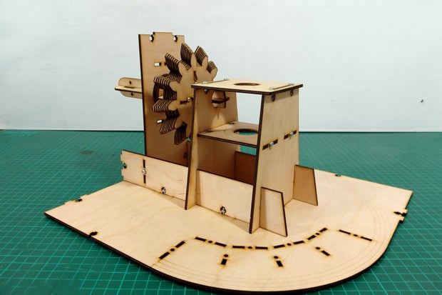
There are two more struts to add to the upright to fix it to the side panel, you'll need another four 10mm bolts for this, and three to secure the bottom of the side panel.
The side panel is the first of the external pieces in this build so if you're planning on finishing the wood it's a good idea to do it before this part of the assembly. I lightly sanded the pieces, and then waxed them with a staining wax. Varnish, Danish oil and paint are all good alternatives, but you'll still also need wax or some other lubricant for the moving parts.

Step 3: Build the Drum


The drum is made of sixteen panels fixed to two hoops, running on four wheels. As well as the laser cut parts you will need four 15mm lengths of 3mm bamboo skewer for the wheel axles.
Start by fixing the sixteen panels to the bottom hoop, with the viewing slots at the top. There is a right way up for the bottom hoop, if the panels don't fit together neatly to form a drum - it's upside down. It's a good idea to glue as well as bolt these pieces in place, that way you can remove the bolts temporarily before you paint it.
Next glue and bolt the top hoop in place. The panels should fit together quite tightly, but there will be gaps. Filling these gaps will make for a better animation effect. I used masking tape on the inside of the joins and a flexible filler applied from the outside. When it's dry sand the joints smooth.
Painting the drum matt black will reduce the light reflected from the outside of the drum between frames. I found it easier to take out the bolts while I did this. I placed the drum inside a cardboard box with all the cracks taped up (to protect the carpet and wall) and spraypainted the drum using many thin layers, rotating the drum once one spray was dry and going over each area about 3 times in the course of many rotations. I also spraypainted the top brackets for the wheels, and the brackets that will hold the film in place (the film brackets needed turning once one side was fully covered and dry). Be careful with it whilst painting; since it has no bolts in it it's a bit more fragile.
The four wheels are made up of two brackets each, one fixed at either side of the bottom hoop. Line up the bottom one, then drop in the wheel and bamboo axle. Place the second bracket over the top and fix in place with 12mm M3 bolts. A little bit of wax or silicon based furniture polish on the axle helps the drum run smoothly.
Finally fix the sixteen brackets to the bottom hoop with 10mm bolts ready to take the animation strips.
Step 4: Build the Crank


The crank is made up of two parts that slot together to form a solid handle. They only fit together one way but it's worth assembling without bolts first to make sure you've got the pieces in the right place. All the parts of this piece are visible externally so should be finished in the same way as you did with the side panel in the previous step before assembly.
- Fix the four external handle parts to the circular piece and the top kidney shaped crank piece. (eight 10mm bolts)
- Slot the two parts of the handle axle to the other crank piece. (four 10mm bolts)
- Slide the two pieces together and use the spacer and two more 10mm bolts to join them together.
Step 5: Put It All Together


Before the top plate is added we need to build the curved shelf for storing spare films.
- Start by adding the four upright back pieces to form a curve (4 10mm bolts)
- Next construct the shelves with the three fin shaped uprights and the curved shelf.
- Fix the two end pieces with two 10mm bolts.
- Slot this structure into the base plate and secure with five more 10mm bolts
The sliding door uses curved rails to keep it in place. Glue and clamp pairs of rails to the top and bottom plates, using the etched guides to align them.
Now you can add the top plate, making sure all the tabs are correctly located. The files I have included are slightly different to the images here, I've taken out some of the bolts shown because they were binding on the wheels. You will need six 10mm bolts.
Slide the door in from the back of the box, making sure the tabs for the handles are first, so that when the door is slid in front of the shelves the handle is on the left. It's worth lightly sanding the top and bottom edges of the door and adding plenty of wax to these edges and the rails.
Next use the three spacers and front piece to form the pouch to hold the 'Now showing' poster. Fix this to the front plate with 12mm bolts.
Screw the front, side and transparent back plates in place.
Use the final two pieces of the crank handle to fix it to the axle of the small gear with 12mm bolts.
The last step is to slot the drum onto the upright axle and secure it with the two semicircular pieces and two 12mm bolts.
The machine is now finished and you should be able to turn the crank to spin the drum.
Attachments
Step 6: Creating an Animation
Hey everyone, this is Snoofers! We figured since I did this part, it might be easier and more sensible if I wrote the steps.
So the first thing I want to point out is that we've provided the same "film" we used in our photos and videos for you to try if you want to; it's called animation.svg. Secondly, we've also provided an svg called "blank strip" that's already the right size to work with this zoetrope, so you can either create digital images and drop them in (if you have snapping active in Inkscape, you should be able to snap the right size images in there) or you can print it off blank and draw them by hand. The right size, by the way, is 67.518 mm by 45.314 mm - sorry about the awkward sizing, there was a lot of trial and error involved in getting the strip to be exactly the right length.
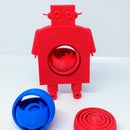
What I found easiest was to use the multiple layers in GIMP to facilitate animation. With only 16 frames, you want to keep it simple, so I just drew "Grobot" who grows and shrinks. To make that easier, I put the "floor," the legs, the arms and the head each on their own layer. That way, I could save the initial image, then move individual parts, then save that image, and so on. Seeing as Grobot is only growing and shrinking, I made 8 frames and then duplicated them again in the reverse order. This achieved two things; it made the animation simple and quick, and it allowed me to duplicate frames 1 and 8 to give him slightly more time at his smallest and at his tallest, which looked quite pleasing in the animated gif I created to preview the animation.
I found that high contrast helps the images be clearer - again, they've moving fast and your eyes have to compensate for the "shuttering" of the drum being spun around. The original animations featured a robot who was white, except for his black outlines, but for the final I went with a darkish grey colour to help him stand out more, and it really made the animation work better in the zoetrope.
I did experiment a fair bit - there's a robot who grows, then flashes green eyes and a green glow from his antenna, a robot who draws a red heart in mid-air with his antenna, and a robot who hasn't got a bobble at the top of his antenna but obtains one from the gloop dripping from the ceiling, then shakes it off and shrinks back down. I found that fine detail is absolutely easily lost in the zoetrope, and colours have to be very bold to stand out, which is why I wound up going (for now!) with a plain grow-and-shrink grey robot. I heartily recommend experimenting though!
To make animated gifs out of my images, I exported them from GIMP as PNGs, then used ImageMagick to turn them into an animated gif. We were aiming for 24 frames per second, so the commandline for ImageMagick was:
convert -delay 4.1 1.png 2.png 3.png 4.png 5.png 6.png 7.png 8.png 8.png 7.png 6.png 5.png 4.png 3.png 2.png 1.png animation.gif
If you're not using Linux or not able to use ImageMagick, there are loads of tools to make individual images into animated gifs - but seeing how an animation works out before you go to the trouble of printing and sticking can be really valuable for minor adjustments like a movement you're not quite keen on now you see it in action, or realising (ahem) that you've accidentally subbed in a white robot with your grey ones. As a random example that definitely didn't happen to me (twice).
To turn your animation into a film strip, once you've pasted your images into the svg file, print them off (I only have access to an A4 printer, so while I've adjusted the document size to fit the strips perfectly for the svg, to print I use a document size of A4 and then print the animation over two pages containing two strips each). Cut them out carefully, whilst trying to leave as little white and as much black as possible. Next, put strip 1 (frames 1-4) and strip 2 (frames 5-8) together face-down, with the black tab after frame 4 overlapping frame 5 on the second strip. Using sellotape, tape over the tab, then using two more strips of sellotape, tape over the little corners you cut out to really secure the two together. Repeat for strips 3 (frames 9-12) and 4 (frames 13-16). Don't stick strip 4 to strip 1, as it'll make it a lot harder to insert the lot into the zoetrope.
Now your strip is ready, carefully slide it behind the upright clips in the drum of the zoetrope. The leftover tab should slot neatly behind frame 1, leaving a perfect array of frames surrounded by plain black.
That's it! You're ready to crank the handle and animate by hand!
Attachments


Participated in the
Epilog X Contest


