

Introduction: Parametric Gyroscope and Robot Made With Tinkercad Codeblocks


This instructable is an introduction to the new Tinkercad Codeblocks, which let you create 3D models using drag-and-drop block code.
I wanted a project that used programming ideas to create something and settled on a version of the gyroscopic fidget toys. These are made by creating a series of concentric hollow spheres and then slicing off the sides. The result is an object that can be printed in one go, but where all the rings are captured together into one toy.
It's possible to make this design using the regular Tinkercad editor but it's a slower process. Using code it is possible to use variables so that the design can be altered to create a toy of any size and with any number of shells.
There are instructions for the gyroscope on it's own, these make a great fidget toy, or cat amuser, or even a flat pack carpet bowls set! I've also included the code for the robot design using this part.
If you just want to download and print off your own gyroscope or robot the STL files are included above.
I don't know of a way to export the code so you will need to create it yourself. Please comment if this is something I'm just missing. I've included screenshots for the code sections and added each piece of code as a code block within the description, e.g.
Create variable MinRadius = 5
Take care with the mathematical functions; the order of the brackets is important!


Step 1: Open the Editor and Get Started

If you've used other block editors like Scratch or Makecode you will be familiar with the idea of block coding; the Codeblock interface is similar to both. Codeblocks uses the basic block shapes that can be grouped together as objects. Objects can be named so that you can reference them in code and make duplicates.
The editor window is split into three sections:
Blocks Menu

On the very left of the editor window are the section headings for the code blocks (Shape, Modify, Control, etc). They are colour coded and represented by circles in the menu. To see the code blocks under each heading, click in the circles. The blocks are shown in a menu alongside the section headings menu. Alternatively you can scroll through all the blocks available using the scroll bar to the right of the blocks themselves.
The sections are:
- Shape - a collection of base shapes that can be used and modified in your code,
- Modify - create and manipulate objects,
- Control - loops used to repeat blocks of code,
- Math - blocks to create variables and perform basic mathematical functions,
- Data - variables created in your code will be available here,
- Markup - blocks to add comments to your code and display messages on the screen as your design is being created.
Code editor

The next part of the screen is where you create the code. Simply drag blocks from the menu here and click them together to form the code. In the bottom right of this screen is a bin, you can drag unwanted code blocks here. This window has horizontal and vertical scroll bars and a zoom function, for times when your code is too big to fit.
Code is run from the top down, so you need to make sure you declare variables higher up the page than you use them, otherwise you will not get the result you're expecting.
Workplane

Finally the right hand side of the screen is where the design will be displayed. It looks exactly like the workplane in the 3d design editor, with a box at the top left that lefts you rotate the design and zoom in/out so you can check it from all angles. At the top of this screen are controls to run your code. The black triangle 'plays' your code, running though each block in turn to create your design (while it does this, the active block will be highlighted). The speed slider controls how fast this runs. Next to the play button is the 'step' button, this lets you execute each line of code one at a time. This is useful for debugging, if something happens you weren't expecting you can quickly spot where your code goes wrong. The last control in this block is undo, which clears the workplane and returns to the start of your code.
Now you're familiar with the layout, it's time to start writing some code!
Step 2: Coding the Gyroscope

Now we can start writing the code for the parametric gyroscope.
The first thing is to grab a Create new object block from the purple 'Modify' section and change the name to Gyroscope. This is going to be the top block of our code.

Next we need to set up six variables to hold the data that will determine how big the gyroscope will be and how many shells it will have. The block for this is Create variable in the green Math section. Drag six of these and connect them underneath the Create new object block.

The variables are;
- minRadius - The size of the smallest shell in the center of the gyroscope
- shellThickness - How thick each of the shells will be
- gapThickness - How thick the gap is between the shells
- numberOfShells - How many shells there will be in total
- percentOfSphere - How much of the complete sphere we'll use eg how thick the finished part will be
- maxRadius - The size of the biggest shell around the edge of the gyroscope This variable is calculated by adding up all the shells and gaps, along with the minimum radius.
Now that we have set up our parameters we can start to make the gyroscope. To make each shell we're going to create a solid sphere with a radius of 'MaxRadius' and another sphere inside that has a radius that is 'shellThickness' less and set to hole. Grouping these two together creates a spherical shell.

Using a repeat block we can loop through this process, each time subtracting another (shellThickness + GapThickness) from the maximum radius. So by the end of the loop we have a set of concentric hollow spheres. The full code for this loop looks like this.
Loop k from 0 to numberOfShells by 1 Solid sphere = maxRadius - k * (gapThickness + shellThickness) Hollow sphere = maxRadius - (k * (gapThickness + shellThickness)) - shellThickness Create group

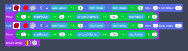
All that's left to do is slice the sides off, this needs two hollow boxes. Again I'm using maxRadius to set the dimensions so that this code works for any size of gyroscope. The width and height of the boxes aren't critical as long as they are bigger than the largest sphere. The length is set to be maxRadius
Because all shapes are created centered at (0,0,0) moving the hollow boxes by maxRadius/2 moves the outer edge to the centre of the sphere. percentageOfSphere tells us how far from the centre of the sphere we place the hollow boxes, to shave off the correct amount at the edges of the gyroscope. It specifies a percentage of the maxRadius, giving us a distance based off the size of the largest sphere.
Note the two minus signs for the second box to move it in the opposite direction.
The last step is to add another 'Create group' block to group everything together.
Move Y = (maxRadius/2) + ((percentageOfSphere/100) * maxRadius)Move Y = (maxRadius/-2) - ((percentageOfSphere/100) * maxRadius)
Running this code should produce an object that looks something like this, depending on the values you've used for the parameters.

Step 3: Exporting the Gyroscope
The gyroscope design is now complete. Using this code, you can make your own gyroscope to your own dimensions and with any number of shells just by editing the initial variables. Experiment with the variables, but be aware that setting the 'percentageOfSphere' variable too thin will mean your shells will not hold together when printed. Conversely, setting the variable too thick will mean the inner sphere(s) may not be visible. I've found 38% to be a reasonable starting point for this value.
At this stage you can export the design as a part and it will be available to use in the regular Tinkercad editor just like any regular block.
Click on 'Export' and then 'Part'. This will bring up a screen where you can give your part a name, a description, and tags. Optionally you can also choose to fix the dimensions with 'Lock part size' so that it can't be resized in the editor. When you have completed this form click 'Save part'. Now when you use the regular editor your part will be available in your 'Part collection' under the 'You' heading in the left hand blocks menu.

Alternatively if you just want to print it you can export the design as a .STL or .OBJ file from the 'Export' menu and save it to your computer just as you would with the 3d design editor.
NB: to print this design it needs to be lying flat on the bed, not upright the way it's produced. I've coded it this way so it's easier to see the robot design in the next step. You should be able to lay it flat in your slicer software or you could add the following blocks to rotate the design and lay it flat on the workplane.
You can print this part without scaffolding and it will come off the printer ready to use.
Rotate around x axis by 90 degreesMove x:0 y:0 z: maxRadius/2

As it is, this design is great as a fidget toy and it's kept cats and humans entertained as a set of carpet bowls. But I promised you a robot with a gyroscope belly, so read on to see the rest of the code.
Step 4: Coding the Robot


To make the robot, I'm using the gyroscope object as in the previous steps. The only difference is I've added an extra move block to lift it up to where the robot belly is going to be.
The arms, legs, ears and eyes are all made with new create object blocks. This lets me easily duplicate them so there is one on each side. One of the quirks of the editor is that defining an object like this creates a copy in the final model, so I've included code to move them in position.
Then I use a new 'create object' block called robot to code the head, body and mouth. Finally, using 'add a copy of' blocks makes it possible to add the other eye, ear, leg and arm; after each block I flip and position the new object.
You can see in the code that I've used the variable maxRadius to set the size and position of all the blocks. This means that if you change the size of your initial gyroscope the robot will resize to fit.
I'll not write out the full code here, it's in the images above. If you copy everything correctly you should end up with a robot that looks like this.
Step 5: Codeblocks - a Very Brief Review..
I really enjoyed getting to know this new set of tools, and have created something that would have been a lot more difficult to accomplish using the existing editor. Being able to make something parametric and easily editable feels like a real advantage. I suspect it depends how your brain works; if you prefer dragging and dropping shapes or writing code to generate them. Both are really useful and have their place, having both together in Tinkercad is great for teaching people new to 3d design. The ability to export a gif animation of the code running as it builds a model is a really nice feature.
It's new and I'm sure there will be changes as it develops, these are a few of the 'quirks' I've spotted.
- In my version of the editor I noticed that not all the shape blocks have the option to set dimensions. Eg the shoulders of my robot are made with a Round roof shape. This can only be created as a 20x20x20 shape, so I had to use a scale block to change the dimensions. Hopefully in future versions all the shape blocks will have the same functionality.
- I wanted to alternate the colours of the shells of the gyroscope part. In Codeblocks this would only be possible with two separate loops one creating the odd shells and one the even shells. Some simple branching code would really help in cases like this. I hope a future version has an 'If' statement built in.
- The control flow of the code seems to run from the top to the bottom of the editor window. I got caught out at first declaring variables lower down the page than they were used. Unlike environments like Scratch, Codeblocks doesn't have any other way to control the flow of the code, and is happy for blocks to run even if they're not connected to anything else. I think this is just something to remember when you are writing code, rather than a tweak for future versions.
- Writing this instructable would have been a lot easier if there were a format to import/export codeblocks! I think part of what makes the maker community so strong is that we are happy to share our ideas for others to build on. Adding a method to share code would be really helpful.
Overall I think Codeblocks is a great addition to Tinkercad. I run a kids' tech club and will be using it as a tool to show children how to create 3d models and look at programming ideas. It doesn't have all the features of software like OpenScad, but the block code interface make it a lot easier to get started with.
If you've not used this part of Tinkercad yet I would definitely recommend exploring this new tool. I hope this project has encouraged to you to get started with Codeblocks!

Participated in the
Plastics Contest


