Introduction: Liberty Bell Replica


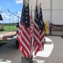
In September, 2010, I volunteered to build a float for a Halloween parade. The theme of the float was patriotic / historical, incorporating historical US flags and a replica of the Liberty Bell. For some time I had wanted to experiment with sculpting with extruded polystyrene (XPS) foam, so this project afforded the oppurtunity to consume scraps of 2" material had saved from my insulating-the-workshop project. At the time I built the replica, I wanted to encase it in fiberglass-reinforced polyester (FRP), but time did not permit. That had to wait until later.
I knew that I could deal with the vulnerable nature of the paper maché and joint compound exterior skin for one parade event. Unfortunately, over the subsequent months, handling and storage of the bell revealed that refinishing with FRP would be necessary and inevitable if I were to keep the bell useful. When I finally found the time to do this, it did not occur to me to take photos of the process. This was partially due to my fear of the resin setting before I was finished working with it (I generally don’t have an assistant). I also did not document making the crown, mounting hardware, yolk, supporting frame, and road case.
Step 1: Materials and Tools
A. Tools
1. Utility knife
2. Wood file/rasp
3. Keyhole saw
4. Bar compass
5. Metal straight edges/rulers
B. Materials
1. White glue (I prefer Elmer's)
2. Rubber cement
3. Spray adhesive (I prefer 3M 77)
4. Gorilla glue
5. Paint brush (I used 1”)
6. Putty knife (I used a 3” taping knife)
7. 2” Extruded Polystyrene
8. Poster board or equivalent (I used the discarded backs from tablets and legal pads)
9. Large paper (I used the reversed side of discarded engineering plans)
10. Newspaper
11. Joint compound
12. Sandpaper
13. Sanding sponge
14. Spray primer
15. Spray paint (I used RustOleum Hammered, Copper)
Note: Selection of adhesive is critical when working with plastics such as XPS, since styrene is soluble in several petroleum distillates, such as acetone. XPS does not appear to be damaged by 3M 77, but is dissolved by 3M 90 and petroleum-based contact cement. Additionally, petroleum-based spray paint can soften XPS and polyester resin attacks it quite aggressively.
Step 2: Establishing Geometry


I found dimensions of the actual Liberty Bell at http://www.ushistory.org/libertybell/more/virtual.htm.
• Circumference around the lip: 12’-0”
• Diameter at lip: 3’-9 13/16” (45 13/16”)
• Circumference around the crown: 7’-6”
• Diameter at crown: 2’-4 5/8” (28 5/8”)
• Lip to crown: 3’-0”
• Height over the crown: 2’-3”
I initially planned to build the replica full size but I decided that this would make it unmanageable; exceed my limited storage space; be too large for the float itself; and would not fit through most doors in my house. I used 75% of the dimensions above. The construction process confirmed the reduction to be a good choice since a full size version would have required more material than was in my scrap inventory.
I downloaded an image from http://www.winnipesaukee.com/forums/showthread.php?t=14356 and inserted it into AutoCAD as a raster. I then traced the outline. I scaled the raster and traced outline to match the 75% dimensions as closely as possible. I then laid out a horizontal grid spaced 2” apart to represent the thickness of the XPS. At the base of each layer, I dimensioned its radius. I also cut out a cardboard negative profile template for use in verifying the shape as sculpting progressed.
Step 3: Making XPS Rings


Most of the XPS scraps were about 3" to 4" wide and 7’-8½” to 8’-0” long. This worked well as material to be cut into trapezoidal segments and assembled into rings in the same manner as done in a wooden wagon wheel.
The first step was to lay out the rings on paper. Using rubber cement, I fastened sheets of discarded engineering plans together to make pieces large enough to draw the rings at full scale. On the reverse side, I drew the rings using a bar compass and laid out the segments. Mimicking the XPS segment layout, I cut segments from the tablet back cardboard and adhered them to the paper using rubber cement to create cardboard-reinforced paper ring assemblies.
I cut the XPS segments on a slide miter saw. After test fitting, I glued them end-to-end into rings using Gorilla Glue and clamped them with a ratchet strap. After the glued segments were firmly connected, I adhered the XPS assemblies to their associated cardboard-paper ring using 3M 77. I then sawed away the material extending beyond the rings and sanded the XPS to a smooth circle.
I then added two intersecting strips of paper to mark the center of the ring and scribed a circle representing the outline of the subsequent ring layer. For each ring that would form a convex portion of the compound curve, I tapered the circumference from its base radius to that of the radius of the subsequent ring layer using a keyhole saw and sandpaper.
Step 4: Build Tapered Section of Bell


Unfortunately, I did not take photographs of each step in building the tapered section of the bell. For the purpose of illustrating this Instructable, I generated a 3-D model of the bell in AutoCAD and produced renderings in 123D.
I cut a corrugated cardboard ring for the base of the tapered section and glued on intersecting corrugated cardboard diaphragms to stiffen the assembly and provide a means of aligning the upper disc. I glued wood hanger strips to the diaphragms. I placed XPS filler blocks at 30-degree intervals to provide additional support for the poster board skin; attached a cardboard upper disc with hanger strips protruding; sanded the XPS blocks to match curve of the ring and disc; and installed the poster board skin.
I glued a plywood disc to the cardboard upper disc, gluing and screwing it to the wood hanger strips. I glued a wood filler cylinder to the plywood disc; drilled a hole in its center for the 7/16” crown alignment dowel; and glued the dowel in place.
Step 5: Stacking the XPS Rings


I applied spray adhesive to the mating surfaces of the rings and aligned the surfaces using the circles scribed on the top of each circle in Step 3. At the previously-tapered rings, I sanded down the XPS until it was flush with the cardboard rings. I test-fit the upper section, sanding the uppermost ring perimeter to allow the skin of the tapered section to fit snuggly around the XPS with the corrugated base ring sitting firmly on the upper surface of the XPS. I did not adhere the tapered section to the XPS at this point because the proportions of the full assembly were such as to prevent me from easily moving it out of the room.
At the lip of the bell, where the curvature is convex, I removed the excess material at the lip using a keyhole saw and wood rasp, then sanded smooth. At this point in the construction, I did not round-over the transition between the lip of the bell and the lower surface of the bell.
Step 6: Initial Finish - Paper Mache and Joint Compound


Using white glue thinned with water, I applied strips of newspaper from the bottom surface of the bell, around the lip, and over the XPS, stopping short of the tapered section. After taking the bell outside, I adhered the tapered section to the XPS; completed the application of newspaper over the joint between the XPS and the tapered section; began applying and sanding joint compound; and glued XPS to the top of the tapered section. After completing the XPS shaping at the top of the bell, I glued paper strips over the top of the bell and coated it with joint compound. After sanding the compound to the desired contour, I primed and painted the bell.
Note: The legs of the original crown extended through the XPS to allow them to be fastened to the plywood disc via screws inserted through the underside of the bell. I revised this configuration when I refinished the bell. The blocking depicted in the renderings in Step 4 is associated with the revised crown.
Step 7: Assembly


I built the yolk from glued-up scraps of lumber that were too small – or too twisted – to be useful in other projects. I ripped, jointed, and planed down pieces to remove any twists and to get straight peices of uniform thickness for gluing. I made the eyebolts and other mounting hardware from steel flats and rods I purchased at the hardware store. I welded flat stock to the ends of rod material, blended the shapes by grinding, drilled the eyes, and threaded the round ends.
Step 8: Refinishing the Bell


As mentioned in Step 6, the original crown extended through the XPS to allow it to be fastened directly to the plywood disc via screws inserted through the underside of the bell. This made the bell structure susceptible to water intrusion through the mortises formed in the XPS on top of the bell. The revised crown configuration eliminated this problem. Wood blocking replaced the legs of the crown that extended through the XPS down to the ¾” plywood disc. The FRP encasement is continuous across the top of the bell, penetrated only at the four screw locations through this added blocking.
The new crown sections are made of a layer of ¾” clear pine laminated between two layers of ¼” plywood. At the screw holes, I drilled oversized holes and filled them with polyester resin. I then coated the entire crown with resin. After the resin hardened, I used a Forstener bit to mill recesses at the screw locations to allow for O-rings that seal the joint between the crown and the top of the bell.
Another improvement is the rounding-over of the lip of bell. I used a ½” round-over router bit and carefully milled the XPS. I then coated the exposed XPS with white glue to protect it from the resin. The FRP encasement extends around lip, across the bottom surface to the inner edge of the ring.
The completed bell is much more durable than the original and is water resistant when in its upright orientation.
Step 9: Road Case


For handling and storage, I built a wheeled road case that contains and protects the bell, the yolk, and the mounting hardware.