

Introduction: MCP23S08 With Arduino


I recently started to think about a project that would require more GPIO pins than my selected micro controller board has. I've used GPIO expanders in the past with great success, so I thought I would turn to them again. I decided on the MCP23S08. It's an 8 GPIO pin SPI based GPIO expander. Shouldn't be too hard to find information on how to use it with Arduino, and get up and going in no time.
But the more I searched, the less I found on using this chip with Arduino. I tried some code, and that didn't work. I watched some videos, and that helped a bit, but not a lot. I looked at examples of using this chip with other systems, and that helped a little bit, too. More searching on the chip without regards to Arduino, and I had a plan.
This instructable will cover a simple Blink sketch on an Ardunio Uno (clone shown in pictures). It hooks up the chip, a diode, and makes it blink.
Supplies
- 1 x Arduino Uno or similar micro controller board
- 1 x MPC23S08
- 1 x LED
- 1 x 220 ohm resistor
- Jumper wires
Step 1: The Circuit

I was able to figure out most of the circuit from the datasheet. To make it a little easier to understand, I drew it up in fritzing.
MPC --> Arduino
Pin 1 --> GPIO 13
Pin 2 --> GPIO 11
Pin 3 --> GPIO 12
Pin 7 --> GPIO 10
Pin 18 --> 5v
Pin 9 --> Ground
Pin 4 --> Ground
Pin 5 --> Ground
Pin 6 --> 5v
Now for the LED. Hook up Pin 10 to the anode of the LED, and run a resistor from the cathode to ground.
Step 2: The Actual Circuit


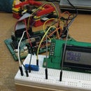
Here are some pictures of my actual circuit. It's difficult to follow the wiring, in my opinion, which is why I started with the fitzring diagram.
Step 3: Intro to the Code
Now, here's the fun part. Actually communicating with the thing.
When you want to interact with the chip, you have to pull the chip select LOW, specify an Address, a Register and a Value, and then pull the chip select back to HIGH each time.
Address
Pins 4 & 5 on the MCP23S08 are the address lines. In my diagram I have pulled them both LOW. The datasheet shows how this works out, but with both 4 & 5 LOW, the address is 0x40. If you're using multiple chips, you could change the settings on 4 & 5 to give you a different address. 4 LOW and 5 HIGH would give 0x43, for example. This is because the least significant bit in this byte is a R/W bit.
Register
All information in the MCP23S08 is stored in Registers. Each register is a byte of data that tells the chip how to operate. There are 11 Registers in total, and when you get more advanced with this chip, using them should be easy. But to start out with, we just need two.
IODIR (0x00) tells the chip what direction the GPIO pins will have. A 0 means OUTPUT, and 1 means INPUT. You can have any combination of INPUTS and OUTPUTS you want.
GPIO (0x09) sets the OUTPUT value of the GPIO pins. You first have to set the direction with IODIR, then you can set the pins HIGH or LOW using GPIO.
Value
The Value is what is passed into the Register. For example, say you wanted to set all pins as outputs, you would send a value of 0x00 to the IODIR register. 0x00 is all 0s, or 8 0s, for the 8 pins. You could send it as Binary if you wanted to--0b00000000. Next, you want to set the first pin HIGH, you send 0x01 (or 0b0000001) to GPIO.
Coding it
I've found it helpful to define a function in my app that actually does the writing to the chip. I just worry about what I'm sending and where I'm sending it. This function looks like this:
void SPIWrite(byte spiRegister, byte value){
  digitalWrite(10,LOW);
  SPI.transfer(0x40);
  SPI.transfer(spiRegister);
  SPI.transfer(value);
  digitalWrite(10,HIGH);
}
First, the digitalWrite pulls the select pin LOW to tell the chip that data is coming in.
Next, we use SPI transfer to send the address (0x40), which tells this chip "I'm talking to you!", the Register, which tells the chip "This is what I'm talking about," and finally the value, which tells the chip "This is what I'm saying."
Finally, the digitalWrite pulls the select pin HIGH to tell the chip the session is over.
This is the key to communicating with the MCP23S08. It's a 5 step process:
- Pull the select pin LOW
- Send the chip the address
- Send the chip the register
- Send the chip the value
- Pull the select pin HIGH
Step 4: Sample Code -- Blink
This code will blink the LED on and off, just like the traditional Arduino Blink sketch.
#include
#includes <SPI.h>
#define SS 10           // The Slave/Chip select pin
#define CHIP 0x40       // The chip's address (set by pins 4 & 5)
#define IO_DIR_REG 0x00 // The Input/Output Register
#define GPIO_REG 0x09   // The GPIO Register

void SPIWrite(byte spiRegister, byte value){
  // This function sends data to the chip
  // It's a 5 step process
  // 1) Pull the Slave/Chip select LOW
  digitalWrite(SS,LOW);
  // 2) Send the chip's address to the chip
  SPI.transfer(CHIP);
  // 3) Send the register to the chip
  SPI.transfer(spiRegister);
  // 4) Send the value to the chip
  SPI.transfer(value);
  //5) Pull the Slave/Chip select HIGH
  digitalWrite(SS,HIGH);
}

void setup() {
  pinMode(SS,OUTPUT);
  digitalWrite(SS,HIGH);
  delay(100);
  SPI.begin();
  SPIWrite(IO_DIR_REG,0x00); // Set all pins to OUTPUT
  SPIWrite(GPIO_REG,0x00);   // Set all pins LOW
 }

void loop() {
  // Set pin 1 HIGH
  SPIWrite(GPIO_REG,0x01);
  delay(500);
  // Set pin 1 LOW
  SPIWrite(GPIO_REG,0x00);
  delay(500);
}
Step 5: Future Thoughts
So, where do you go from here?
First, you can play with the INPUT functionality of the chip. There's even a GPPU pullup resistor Register that lets you use internal pullups in your project. I've worked out some code for this, and will be updating this instructable soon. You can also work with interrupts, but I don't think I can do a drop in replacement for the attachInertupt function. I can get close, but not quite there. I'll update this instructable when I get there.
Next, you can look into the MCP23S017, which is a 16 pin version of this chip, and most likely (I haven't checked it out yet) functions very similarly.
Finally, and this is what I'm working on, you can create a library that lets you do a drop in replacement for pinMode, digitalWrite and digitalRead. For example, I coded up my library with drop in replacements for pinMode and digitalWrite. Next I made a copy of the LiquidCrystal library, and added my library to it. Finally, I did a quick search and replace, replacing pinMode and digitalWrite with my functions. It worked beautifully, and now I have a LiquidCrystalMCP library where I can run the LiquidCrystal display from the MCP23S08.
Good luck, and have fun!

Participated in the
Arduino Contest 2019


