

Introduction: Make Your Hydroponics System Fully Automated and View Data Via the Dashboard


This project shows how to control the hydroponic system as automation and how to monitor the desired data through applications. First of all, I should mention that I am not familiar with hydroponics and soilless growing culture. With this project, I experienced hydroponics for the first time. The main point of this project is to activate the sensors included in the system and the water pump motor at intervals determined as automation, and then view the system operation and sensor data on a dashboard.
Step 1: Germinating Seeds


We start the first section by sowing the preferred vegetable seeds for germination, so the seeds will reach the desired seedling level by the time they are included in the project. Lettuce is one of my favorite vegetables to grow. And it also grows very fast, which makes it an ideal choice for beginners in hydroponics. I chose organic peat soil for germination, but later in the project I realized that it has some disadvantages, so I decided that agricultural rockwool or growing sponge would be a better option. After sowing the seeds, water them frequently to speed up germination and keep them in a covered box.
Step 2: Required Sensors, Water Pump Motor and Microcontroller


In this section, we will take a look at the electronic equipment to be used in the system. 12-volt water pump motor, pH sensor for water pH measurement, level sensor for water capacity measurement, 12-volt power adapter to power the circuit, adjustable voltage module for the 5-volt power requirement of the microcontroller, and of course a Wi-Fi-based microcontroller will be used.
Step 3: Printed Circuit Board
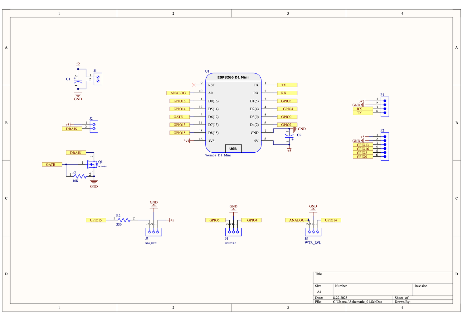


Since the breadboard circuit will be very complex, I will use my own design PCB. The Altium Designer system was preferred for printed circuit board design. Altium Designer offers engineers a unified environment that provides a comprehensive view of the entire PCB design process. This includes schematic, PCB layout, harness design, and documentation, empowering engineers to access all necessary tools in one place.
Get a free trial of Altium Designer with 365 the world’s most trusted PCB design software, and 25% off your purchase https://www.altium.com/yt/maker101io
A more detailed video will be shared for the full design process of the PCB for the project. For now, the highlights are that a Wemos D1 mini library was created first. Then the Altium Designer component library and Octopart, a free component search engine, were used to find and include the necessary electronic parts and components for the circuit. Octopart provides part documentation, including datasheets & CAD models. Once all components have been added to the circuit diagram, the circuit connection phase begins.
In the meantime, if you need support during the design process and teamwork is required, Altium 365 is the best solution. Introducing Altium 365, the world’s only cloud platform for printed circuit board design and realization. Try Altium 365 for FREE! https://www.altium.com/altium-365
Attachments

Step 4: Ordering and Soldering the PCB


After exporting the PCB files with a single click, the ordering process begins! PCB printing quality is as important as board design, I prefer PCBWay, which offers an affordable price and high-quality PCB printing service. All you need to do is upload the PCB files you created and complete the order. In addition, PCBWay meets many needs with its wide range of services.
Cheap & Quick PCB, 3D Printing, CNC machining, and fabrication services from PCBWay https://pcbway.com/g/v8fQIG
Once the printed circuit board is delivered, the necessary components are prepared and the soldering process begins. The components are placed on the board according to the shared reference designator and then fixed with a soldering iron and soldering wire.
- C1, C2 - 16V 100uF Capacitor
- U2, U3 - 5.0-2P Connector for Power and Pump
- U4, U5, U6 - 5.0-3P Connector for Sensors and NeoPixel
- U1 - 2.54-1*16P Female Header for Wemos D1 Mini
- H1 - 2.54-1*4P Male Header for External Pins
- H2 - 2.54-1*6P Male Header for External Pins
- R1 - 330ohm Resistor for NeoPixel Digital Pinout
- R2 - 10K Resistor for MOSFET
- MOSFET1 - TO-220-3 IRFZ44N MOSFET
Gerber and PCB Files: https://www.pcbway.com/project/shareproject/Make_your_Hydroponics_System

Step 5: Circuit Power Requirement and Pump Testing

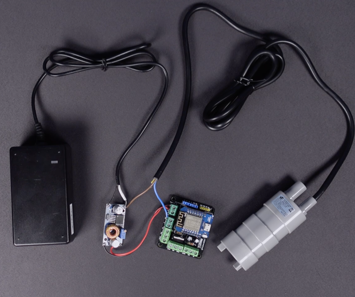


In this section, we will connect the voltage regulator module. The water pump motor runs on a 12-volt voltage, so a 12-volt power adapter is used. A voltage regulator module is used to provide the 5-volt voltage required by the microcontroller. To the positive power input of the regulator, the positive legs of the adapter and the positive leg of the motor are connected in common. Only the ground leg of the adapter is connected to the regulator's ground input. The power outputs of the regulator are connected to the power inputs of the circuit board. The ground leg of the motor should be connected to the MOSFET ground input to will be triggered via the digital pin. You can reduce the input voltage to the desired output voltage value via the potentiometer on the adjustable voltage regulator. After completing the power connection of the circuit, we uploaded and tested the shared source code for motor control and the circuit worked successfully.
Attachments
Step 6: PH Meter Sensor Test


Let's test the pH meter, another sensor we use in the system. pH meter measures analog value and the signal input of the module is connected to the Analog 0 pin in the circuit, while the power inputs of the module are connected to the 5-volt and ground line of the circuit. Open the shared code for the pH meter, the Wi-Fi board analog pin in the circuit reads an analog voltage value from 0V to 3.3V, and the code is prepared according to this. If you are using a different board, this value should be updated with the analog voltage value provided by the board. Upload the code to the circuit, then turn on the serial monitor and observe the values. Since the pH probe has not yet been in contact with a liquid, the values are high as can be seen, now let's immerse the probe in tap water. The pH of water can vary depending on several factors, including the weather, but tap water typically has a p-H of about 7.5. We will touch on the pH value required for a hydroponic system later. As you can see, the code and the circuit work successfully.
Attachments
Step 7: Liquid Level Sensor Test


Now let's connect the liquid level sensor to the circuit and test it. The level sensor signal input is connected to the digital pin of the board, the sensor power input is also connected to a digital pin and will be powered by the HIGH signal only at the time of measurement. The reason for this is to extend the life of the sensor, which is constantly exposed to liquid, and to ensure that it can be used for a longer period of time. Open the shared code and make the necessary pin updates, then load the code and turn on the serial monitor. Immerse the sensor in the liquid and observe the printed data, as you can see the liquid sensor works successfully.
Attachments
Step 8: Servo Motor


Finally, we added a Mini Servo motor to the circuit in order not to expose the PH meter to the liquid continuously. A simple and basic Servo motor control code was used to immerse the PH meter in and out of the liquid at the specified time interval. In the next step, we will prepare the water tank.
Step 9: Preparation of Water for Hydroponic System


After the servo motor and liquid level sensor were attached to the water tank, approximately 15 liters of tap water were used. PH-balancing liquids are necessary to adjust the PH balance required by the plants preferred for growing. Since the PH value of tap water is higher than the value required by the plants, PH-lowering liquid was used. The PH-lowering liquid is added to the tank in a controlled way, while the PH value is observed via a PH meter and serial monitor. When the desired PH balance is reached, add the special nutrient solution needed for the plants. An EC meter should be used for conductivity, tap water conductivity is normally low and as PH is added to the water first, the conductivity of the water comes closer to the required EC value. The nutrient solution contains two different mixed nutrients for the plants, A and B. As this is a bit complicated you can find a link to an explanation in the description. The most important point here is to add equal volumes of nutrients A and B to the water. The ideal EC value is stated to be about 1000 microsiemens/centimeter.
Step 10: Assembling the Hydroponics System Structure


In this section, let's finish the preparation of the water tank and move on to the construction of the hydroponic system. For the hydroponic system, I had a ready-made set in my workshop and I used it. The skeleton of the set consists of PVC pipes. If we talk about the working principle, first of all, the water in the tank is transferred to the top layer through the pump. The pump hose is independent from the bottom layer and the water from the tank goes directly to the top layer. When the top layer reaches sufficient water level, the water passes to the bottom layer, and then the bottom layer is filled with sufficient water. Periodically the pump is restarted and water is transferred back to the top layer, while the water that has accumulated on the layers is transferred back to the tank through the drainage section. This working principle continues as a cycle. The drainage and pump hose are independent from each other and the return of the water from the top layer back to the tank from the opposite direction is prevented by a blind plug.
Step 11: Placing the Plants and Some Advice


The system is installed and now the plant seedlings can be placed in the system. In about 15-20 days the plants have reached this size, temperature, lighting, and adequate watering are the factors that make the plants grow fast. In the section on germination, I mentioned the disadvantages of peat soil and suggested using agricultural rock wool or growing sponges for germination. This is because during irrigation some particles from the peat soil get into the water tank, which can clog the pump. In order not to waste these plants, I will wait for them to grow, in the meantime I protected the water inlet of the pump by covering it with a plastic bottle and a coffee filter. For the next plant germination, I used a growing sponge, so I don't have to protect the pump inlet.
Step 12: Source Code and Dashboard Application


Let's take a look at the all-in-one source code for the whole system. We chose Blynk, a popular tool for monitoring system data. At the beginning of the code, there are some definitions obtained from the Blynk application.
#define BLYNK_PRINT Serial
#define BLYNK_TEMPLATE_ID "YOUR_ID"
#define BLYNK_TEMPLATE_NAME "Hydroponic Home"
#define BLYNK_AUTH_TOKEN "YOUR_TOKEN"
After logging into Blynk, create a template and get the unique token address, template name, and template ID. Then create three virtual pins, a double data type for the PH sensor and a string data type for the status of the level sensor and the motor. In the Dashboard section, add a Chart and a Gauge for the PH sensor, then a Label for the water level and motor status. Besides the web browser, you can create this template in the smart device app and monitor the system.
Then install the necessary libraries used in the code. Define your Wi-Fi network information, then define the pins to which the components are connected.
#include <Servo.h>
#include <ESP8266WiFi.h>
#include <BlynkSimpleEsp8266.h>

Servo phServo;

char ssid[] = "MAKER101IO";
char pass[] = "maker101.io";

#define PH_PIN A0
#define LVL_PIN 15
#define LVL_PWR 4
#define WATER_PUMP 12
#define SERVO_PIN 2
Define how often the system will be switched on and how long the pump will be activated. For now, the system is activated every 60 seconds and the pump runs for 3 seconds. If you used a servo motor, define the starting position of the servo.
#define TIME_RANGE 60000
#define PUMP_TIME 3000

int pos = 170;
Then, the code block created for the PH sensor was added. We mentioned the analog voltage value, which is the important point here. In addition, the value to be sent to Blynk was added and servo motor movements were defined.
/*--------- pH Sensor ---------*/
unsigned long int avgValue;
float b;
int buf[10], temp;

int f;
float val;
char buff2[10];
String valueString = "";
String Value = "";

void PH_Value(){
  for (pos = 170; pos >= 10; pos -= 1) { // goes from 170 degrees to 10 degrees
    // in steps of 1 degree
    phServo.write(pos);              // tell servo to go to position in variable 'pos'
    delay(10);                       // waits 15ms for the servo to reach the position
  }
  delay(2000);
  for(int i=0; i<10; i++){
    buf[i] = analogRead(PH_PIN);
    delay(10);
  }

  for(int i=0; i<9; i++){
    for(int j=i+1; j<10; j++){
      if(buf[i] > buf[j]){
        temp = buf[i];
        buf[i] = buf[j];
        buf[j] = temp;
      }
    }
  }
  avgValue=0;
  for(int i=2; i<8; i++)
  avgValue+=buf[i];
  float phValue = (float) avgValue * 3.3/1024/6;
  phValue = 3.5 * phValue;
  Value = dtostrf(phValue, 4, 2, buff2);
  Serial.print("pH Value: ");
  Serial.print(Value);
  Serial.println("");
  valueString = "";
  delay(500);

  Blynk.virtualWrite(V1, Value);
  delay(2000);

  for (pos = 10; pos <= 170; pos += 1) {
    phServo.write(pos);
    delay(10);
  }
}
Then, the code block for the water level sensor was added. The values to be sent to Blynk were defined.
/*--------- Water Level Sensor ---------*/
void readWaterLevel(){
  digitalWrite(LVL_PWR, HIGH);
  delay(1000);
  int waterLevelVal = digitalRead(LVL_PIN);
  if(waterLevelVal == HIGH){
    Serial.print("Water Level: ");
    Serial.print(waterLevelVal);
    Blynk.virtualWrite(V2, "Water Level Good");
  }
  else {
    Blynk.virtualWrite(V2, "Need to Add Some Water");
  }
  delay(2000);
  digitalWrite(LVL_PWR, LOW);
}
Then, the function to run the water pump was added, and again the values to be sent to Blynk were defined here.
/*--------- Water Pump ---------*/
void runWaterPump(){
  digitalWrite(WATER_PUMP, HIGH);
  Blynk.virtualWrite(V3, "Water Pump Started");
  Serial.print("Water Pump: ");
  Serial.print("HIGH");
  delay(PUMP_TIME);
  digitalWrite(WATER_PUMP, LOW);
  Blynk.virtualWrite(V3, "Water Pump Stopped");
  Serial.print("Water Pump: ");
  Serial.print("LOW");
}
Before the setup section, two variables were defined to track and reset the time interval.
/*--------- Time Range ---------*/
/* Define the time range for sensor measurements */
const int measurementInterval = TIME_RANGE;
/* Time variable to keep track of the time range */
unsigned long previousMillis = 0;
In the Setup section, the standard network connection and serial communication protocol are initialized, and Blynk settings are defined. Finally, pin modes and pin states are specified.
void setup() {
  Serial.begin(9600);
  WiFi.begin(ssid, pass);
  while (WiFi.status() != WL_CONNECTED) {
    delay(500);
    Serial.print(".");
  }
  Serial.println("");
  Serial.print("Wi-Fi connected: ");

  Blynk.config(BLYNK_AUTH_TOKEN);

  phServo.attach(SERVO_PIN);
  phServo.write(pos);

  pinMode(LVL_PIN, INPUT);
  pinMode(LVL_PWR, OUTPUT);
  pinMode(WATER_PUMP, OUTPUT);

  /* Initially keep the sensors and motor OFF */
  digitalWrite(LVL_PWR, LOW);
  digitalWrite(WATER_PUMP, LOW);
}
In the Loop section, Blynk is activated and the time interval is calculated, then the functions are executed.
void loop() {
  // Run the Blynk app
  Blynk.run();

  /* Get current time. If the defined time range
  has not passed, terminate the loop */
  unsigned long currentMillis = millis();
  if (currentMillis - previousMillis < measurementInterval) {
    return;
  }
  /* If the defined time range is complete, update the time */
  previousMillis = currentMillis;

  PH_Value();
  delay(2000);
  readWaterLevel();
  delay(2000);
  runWaterPump();
  delay(2000);
}
Let's upload the code, place the plants, assemble all the circuits of the system, and let's run the hydroponic system! The whole system is running successfully, maybe later we can build a fully automated hydroponic system that will automatically add the necessary solutions to the water using an EC meter sensor and Peristaltic Liquid Pumps. You can share your ideas in the comments section, thanks for reading.


