

Introduction: Make a Simple Wireless RF Robot Using Arduino!


UPDATE : I'VE ADDED JOYSTICK CONTROL TO THIS ROBOT. PLEASE REFER TO THE STEP 7 IF YOU WANT TO CONTROL YOUR ROBOT VIA JOYSTICK.
Hi,
This is my first instructable and in this tutorial, I'm going to show you, how to build a simple wireless robot using Arduino and simple RF modules (the ones that you get for $1 US nowadays on eBay).
You may think that Bluetooth modules might be a more simple and effective way to make wireless bots, but lets face it, bluetooth modules are a tad pricey than these cheap buggers (You may argue over that, but in my country the HC-06 bluetooth module is around 3 times the price of RF modules). And also, I want to keep the budget low, so digging in this project isn't going to be much costly :-)
The main thing about this project is that you will be punching keys on your keyboard and making the robot move accordingly. This is a very crude project, and you can make it better by making a GUI, which can be built easily using Processing. So, here we are going to punch in the commands in the serial monitor of the arduino connected to the host computer; the arduino will read the data put in and send it out via the transmitter. The arduino on bot will catch the signal through a receiver and will act accordingly (like move the motors forward when 'w' is pressed).
I have taken help from various tutorials and the arduino forums. So first of all, I want to thank the great people who helped me up in the forums. I got the codes from this website listed below, and tweaked them as per my requirements.
http://www.libremechanics.com/?q=node/31
So , I wanna thank the author for sharing this code !
I will try to keep things as simple as possible. If any of you have questions, feel free to post them in comments or email me at vinutyagi@gmail.com
So, lets jump right into it. Hope you'll enjoy it :-)
Please keep reading the notes given alongside the pictures. They'll help you. Take my word for it :-)
-------------------------------------------------------------------------------------------------------------------------------
UPDATE : I'VE ENTERED THE FULL SPECTRUM CONTEST. PLEASE VOTE FOR THIS ROBOT! THANKS
---------------------------------------------------------------------------------------------------------------------------------
Step 1: Materials Required :


Here I have given the list of things you are going to need to build this robot. I'd like to keep it all encompassing so you won't need to visit the supplies store again and again...
Electronics :
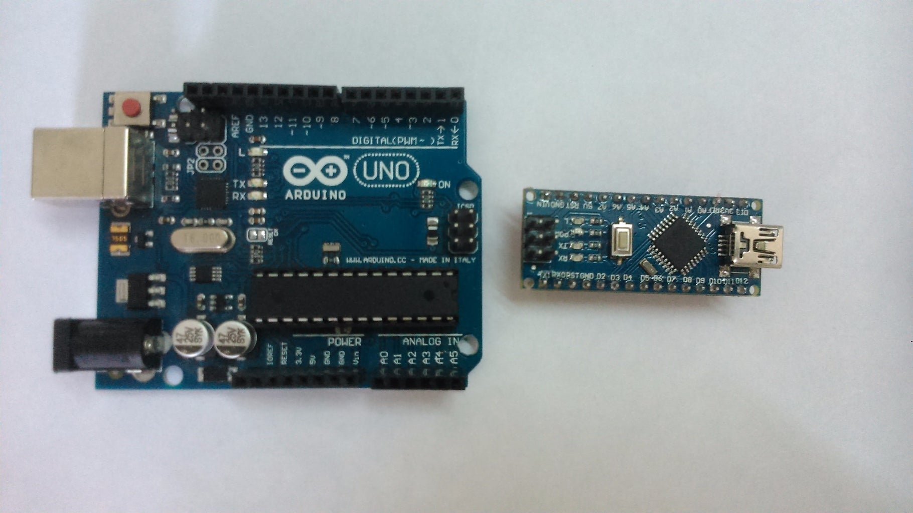
1) Two Arduinos ( I have used the Uno and the Nano,all compatibles will work fine too)
2) 433 MHz RF transmitter and receiver modules
3) 2 Breadboards (I have used the half+ and mini)
4) Jumper cables (Around 7-8 male to male and a few female to male/ female to female jumpers)
5) Adafruit Motor Shield v 1 compatible (I know its too old, but its more comfortable to me, as it's the only one available here)
6) HC-SR04 ultrasonic sensor (optional, just for decoration)
That's it for the electronics, for the physical structure, you need :
1) Chassis (You can build it out of wood, cardboard, acrylic etc. or you can buy it off online, which is what I did)
2) 2 Battery Operated (BO) geared DC motors with fitting wheels (Mines I cheap plastic ones, but you can buy better metallic ones)
3) Castor/Caster wheel
4) Nuts and bolts fitting with your chassis
5) Double sided tape (optional)
6) 9V batteries ( So, we need one for the Arduino, and one for the motor shield)
7) Arduino IDE installed on the computer, with the VirtualWire and AFMotor library installed.
Virtual Wire library - http://www.airspayce.com/mikem/arduino/VirtualWire...
AF Motor library - https://github.com/adafruit/Adafruit-Motor-Shield-...
(See the instructions on the website given for proper installation)
8) Solder iron and soldering wire
9) Single core wire (length around 34 cm. We'll be using them as antennas on my RF modules. Cut the wire in half to have 17 cm of wire each for the transmitter and receiver)
10) USB cables to upload codes from the Arduino IDE onto the Arduino.
11) Screwdriver ( I used a flat head screwdriver)
12) Male header pins
That's all for the materials. Now 'speak hands for me' ;-) . Let's get started !
Step 2: Set Up the Transmitter Side of Things

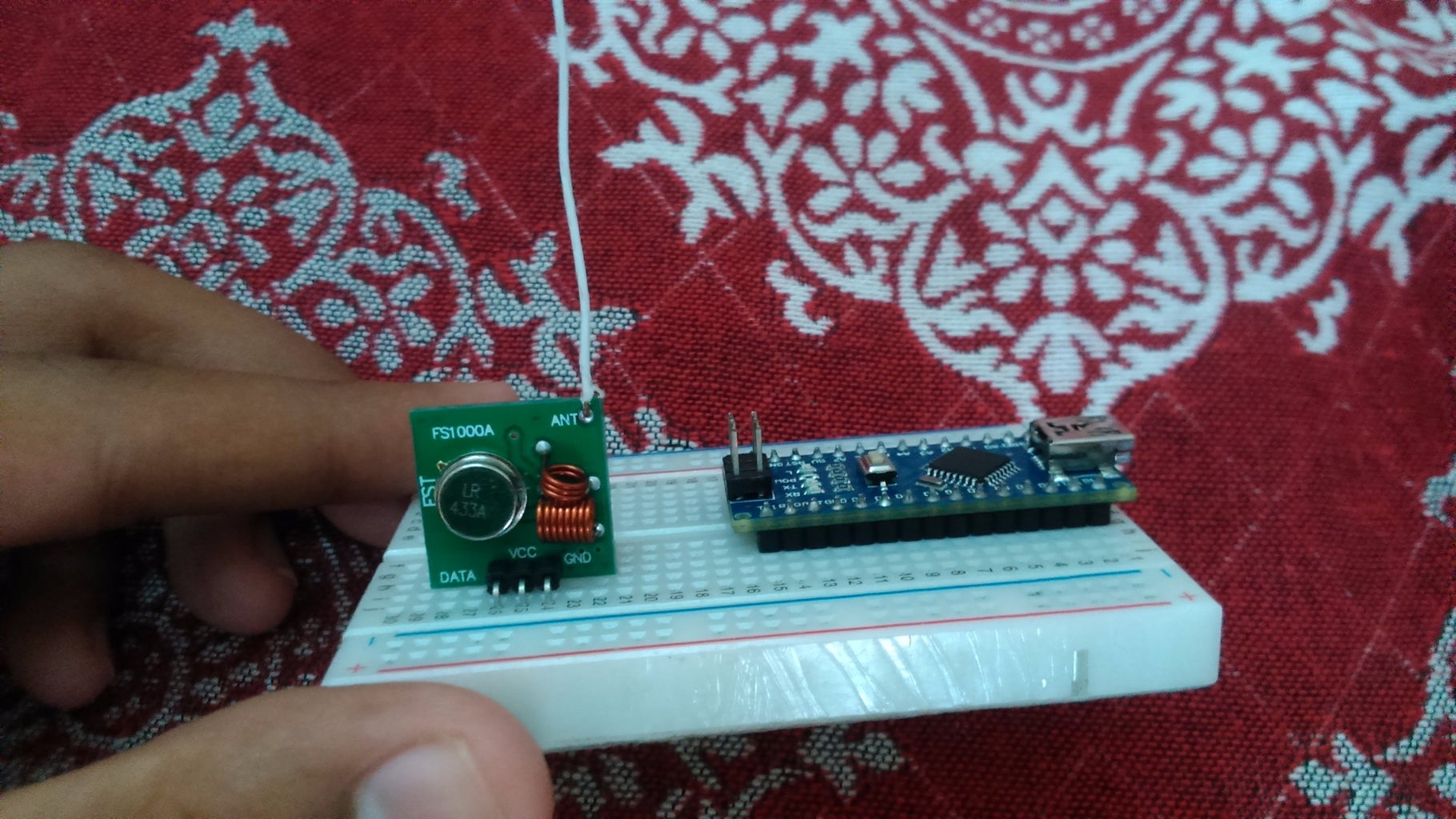


First of we need a base station (kind of!) to send off our commands. For that, we are going to need an arduino (I used the Nano), the RF transmitter and 3 male to male jumper cables.
Solder a 17 cm single core wire to a hole named ANT (antenna) on the upper right edge of the transmitter module.
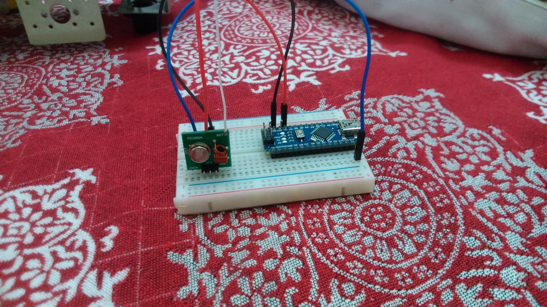
The transmitter has 3 pins ( DATA/ATAD, VCC, GND (left to right)). Connect the data pin to the D12 (digital pin 12) to the DATA (or ATAD) pin on the Arduino using male to male jumper. Then hook up VCC to 5V on the Arduino. And of course, connect GND to ground.
That's all for our makeshift base station!
Step 3: Settling the Receiver Side of Things


Now that we have built the base station, we need a receiver , that will work catch the commands sent by the transmitter and obey them accordingly. For the receiver end I used the Arduino Uno.
First of all, solder a 17 cm wire to a hole given on the bottom right edge of the receiver module.
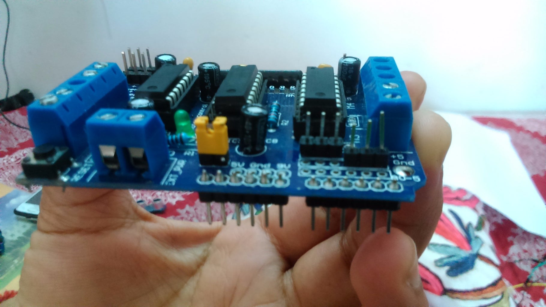
We need to have a 5V supply for the receiver, which is not possible when I stack the motor shield on top of the Uno. But we have a fix for that ! Look on the bottom right corner of the motor shield and you'll see breakouts for 5V, GND , and A0-A5. We can solder male headers on the Motor Shield breakouts, and then jump 5V and GND onto our mini breadboard using female end jumpers. Also notice a small breakout for pin 2 on the motor shield. Solder a single header onto the breakout and jump the pin 2 onto the mini breadboard. Neat!
Now take a look at the receiver. The pins from left to right are
GND, DATA , DATA and VCC.
Hook up the GND jumper from the breakout on the motor shield to the GND on the receiver end.
Hookup the digital 2 pin broken out from the motor shield onto one of the DATA pins (We're gonna use only one of the DATA pins)
And finally jump the 5V to VCC again, taken from the breakout on the motor shield.
Here you have it, your receiver is done.
Step 4: Mounting the Arduino + Motor Shield + Receiver on the Chassis


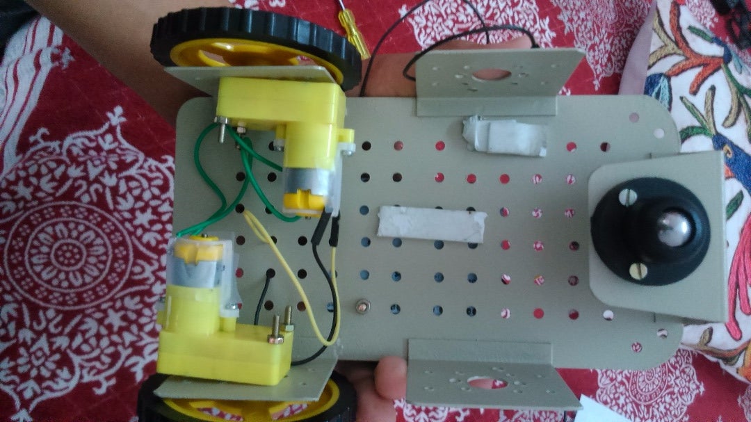

Take your chassis and plant the arduino on it using nuts and bolts given on the holes in the arduino and the motor shield.
Look carefully at the motor shield. You'll see two columns of blue colored terminal blocks on the lateral sides of the shield. There will be markings M1, GND, and M2 on the left side terminal blocks and M3, GND, and M4 on the right side terminal blocks. You wont be needing the right side terminal blocks.
Take a screwdriver and rotate the screws on the terminal blocks anti-clockwise (to open them). Make enough space for the motor wires to slide in. Take one of the BO motors, and put its wires in the two terminal blocks on the M1 channel. Then take the other motor, and put its wires in the M2 channel of the shield. Leave the GND as its not required right now.
Place the motors in the correct places as per your chassis. You now have a 2 wheel drive!
Take a small amount of double sided tape and put it on the anterior end of the chassis. Place the mini breadboard with the receiver module on it, and press it to secure it to the platform.
And finally, place the caster wheel on the chassis using nuts and bolts. You can use an old bottle cap and hot glue it on the chassis to have a good balance.
You now have something called a robot!
PS- please read the notes on images to have a better understanding of the procedures.
Step 5: Uploading the Codes
Take your transmitter + Nano (AKA Base station) and plug it into the computer via a mini USB cable. Upload the following code that I took from a tutorial on the web (I mentioned it on the intro page), onto your arduino connected to the transmitter.
Upload the receiver code into the Arduino Uno.
Transmitter code and receiver codes are given here :
Attachments

Step 6: Making the Robot Move !
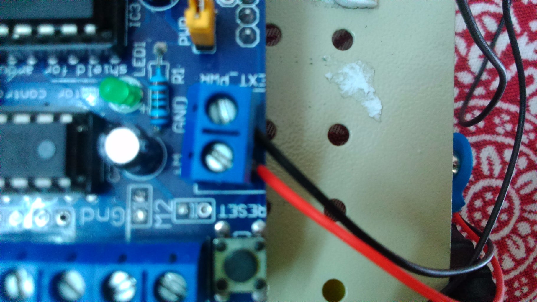
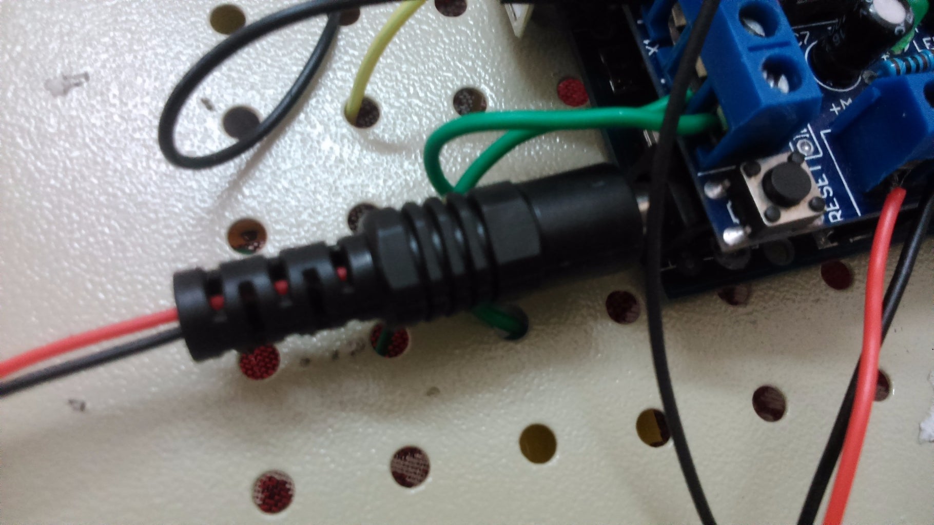


Plug in a 9V battery in the Arduino Uno using a barrel connector. Look for a pair of terminal block named EXT_PWR on the motor shield. It indicates you can add external power to the motors via this pair of blocks. Plug in the positive (red) wire of the strap connector of your other 9V battery. Also plug in the black (GND) wire of your connector to the the shield.
Once you're done with powering, jump to the computer and plug in the base station. Select the appropriate COM port on the Arduino IDE and click on the serial monitor. Punch in a w (not capital w) in the space given for typing. Click 'send' or press enter. If you've followed the tutorial correctly, you'll see the robot moving forward. Voila! you've done it!!
If it doesn't move, check the connections again and try. I you face any problem feel free to post in the comments or e-mail me at vinutyagi@gmail.com
If the robot is moving the other way than what you command, please interchange the wires on the motor channels.
Thanks for watching, and please share any modifications and suggestions.
Step 7: Improving Robot Control


It might seem a little tedious to hit the enter key every time if you want to send data through the serial monitor. This was the only drawback of the control of the robot and also, you cannot carry your PC everywhere. So to make things better, I introduced joystick control to the robot. You can buy a a thumb joystick module for around $2. Rest everything will be the same.
Here you can buy the joystick module.
Take your base station (Nano + transmitter), and hook up the thumb joystick to the base station according to the fritzing diagram I made. Once everything is hooked up, you can contain your controller in a box, or a 3 D printed fancy box, if you're lucky enough to have a 3 D printer. I made mine out of cardboard. It may not look good, but works fine for me.
There is no need to change the receiver code, I have made the transmitter code such that there will be no need to change it.
I didn't have the switch pin on my joystick module, so I didn't include it in the circuit diagram. But if you have it, you can assign it some job, by connecting the switch pin to any of the digital pins, and reading the switch value using the digitalRead function.
First upload the JoystickTest code on your base station and open the serial monitor straightaway. Note down the values for various motions (forward, left, right and back) from the serial monitor. If you get the same values as me, fine. If you don't, change the values to your values in the RFwithJoystick code in the 'if' function.
Thanks for watching! Post your queries below or email me at vinutyagi@gmail.com

Participated in the
Full Spectrum Laser Contest 2016


