

Introduction: Measuring Humidity Using Sensor (DHT11)


The percentage of water present in the air is termed as humidity. Water as gaseous state called vapor. As the temperature of the air increases more water vapor can be generate.
Humidity measurement in industries is critical because it may affect the business cost of the product and the health and safety of the personnel. So, its huge importance of humidity sensor is very important, especially in the control systems for industrial processes like chemical gas purification, dryers, ovens, film desiccation, paper and textile production, and food processing. In agriculture, measurement of humidity is important for plantation protection (green house), soil moisture monitoring, etc.
Types of humidity:---
1) Relative Humidity = (density of water vapor / density of water vapor at saturation) x 100%
2) Absolute=Mass(vapour) / volume. Unit-grams/m3
3) Specific:Mass(vapour) / total mass.
4) Dew Point:Temperature(above 0°C) at which the water vapor in a gas condenses to liquid water)
5) Frost POINT: Temperature(below 0°C) at which the water vapor in a gas condenses to ice
Most Common:
- Relative Humidity (RH),
- Dew/Frost point (D/F PT) and
- Parts Per Million (PPM) are used.
RH is a function of temperature, and thus it is a relative measurement.
Dew/Frost point is a function of the pressure of the gas but is independent of temperature and is defined as absolute humidity measurement.
PPM is also an absolute measurement.
Step 1: Working of Humidity Sensor


Most humidity sensors use capacitive measurement to determine the amount of moisture in the air.
This type of measurement relies on two electrical conductors with a non-conductive polymer film laying between them to create an electrical field between them. Moisture from the air collects on the film and causes changes in the voltage levels between the two plates. This change is then converted into a digital measurement of the air’s relative humidity after taking the air temperature into account. Above figure can clear your doubt.
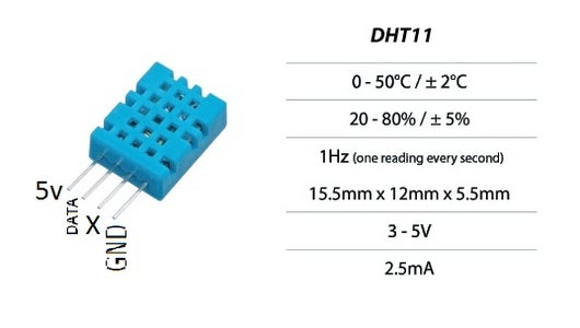
DHT11 Technical Specifications:
Humidity Range: 20-90% RH
Humidity Accuracy: ±5%RH Temperature Range: 0-50 °C Temperature Accuracy: ±2% °C Operating Voltage: 3V to 5.5V
The DHT11 calculates relative humidity by measuring the electrical resistance between two electrodes.
The humidity sensing component of the DHT11 is a moisture holding substrate with the electrodes applied to the surface. When water vapor is absorbed by the substrate, ions are released by the substrate which increases the conductivity between the electrodes. The change in resistance between the two electrodes is proportional to the relative humidity. Higher relative humidity decreases the resistance between the electrodes while lower relative humidity increases the resistance between the electrodes.
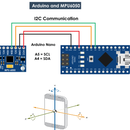
The DHT11 converts the resistance measurement to relative humidity on an chip mounted to the back of the unit and transmits the humidity and temperature readings directly to the Arduino Nano.
Step 2: Circuit-Diagram of Sensor(DHT11) With Atmega32 and LCD


Connect as links given in diagram.
The above circuit diagram shows interfacing of ATmega32 to DHT11 sensor.
In that, DHT11 sensor is connected to PD6 (Pin no. 20)
Step 3: Sensor - DHT11 (contd....)


DHT11 Sensor Interfacing with ATmega32.
DHT11 is a single wire digital humidity and temperature sensor, which gives relative humidity in percentage and temperature in degree Celsius.Introduction DHT11 is a single wire digital humidity and temperature sensor, which provides humidity and temperature values serially.DHT11 sensor provides humidity value in percentage in relative humidity (20 to 90% RH) and temperature values in degree Celsius (0 to 50 °C) DHT11 sensor uses resistive humidity measurement component, and NTC temperature measurement component.
Some Facts:
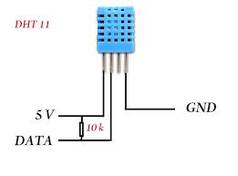
>>DHT11 is 4 pin sensor, these pins are VCC, DATA, GND and one pin is not in use, shown in fig above.
>>Communication with microcontroller DHT11 uses only one line for communication.
>>The voltage levels with certain time value defines the logic one or logic zero on this pin.
>>The communication process is divided in three steps,
------------->first is to send request to DHT11 sensor,
------------->Second, sensor will send response pulse and
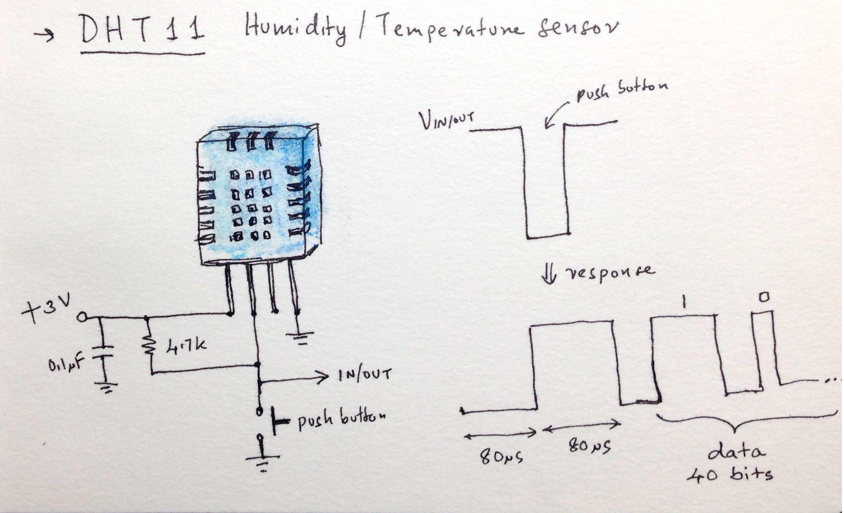
------------->then it starts sending data of total 40 bits to the microcontroller.
Start pulsE:To start communication with DHT11, first we have to send the start pulse to the DHT11 sensor.To provide start pulse, pull down the data pin minimum 18ms and then pull up, as shown in START-PULSE figure.
Outputs:
>> After getting start pulse from the controller, DHT11 sends the response pulse to the microcontroller which will indicate that DHT11 received start pulse.
>>The response pulse is low for 54us and then goes high for 80us.
>>After sending the response pulse, DHT11 sensor sends the data, which contains humidity and temperature value along with checksum. The data frame is of total 40 bits long, it contains 5 segments (byte) and each segment is 8-bit long.In this 5 segments first two segments content humidity value in decimal integer form. This Value gives us Relative Percentage Humidity. 1st 8-bits are integer part and next 8 bits are fractional partNext two segment content temperature value in decimal integer form. This value gives us temperature in Celsius form.
>>Last segment is the check sum which holds check sum of first four segment.Here checksum byte is direct addition of humidity and temperature value. And we can verify it in microcontroller whether it is same as checksum value or not. If it is not equal, then there is some error in the data value otherwise the data is correct.Once microcontroller receives data, DHT11 pin goes in low power consumption mode until the microcontroller do not sends start pulse again.
End-Pulse
After sending 40-bit data, DHT11 sensor sends 54us low level and then goes high. After this DHT11 goes in sleep mode.
Step 4: Programming

Programming of DHT11:
/*Define pin no. to interface DHT11 sensor, in our program we define PD6 (Pin no. 20).
Send the start pulse to DHT11 sensor, making low to high.Receive the response pulse from the DHT11 sensor.After receiving the response, receive 40-bit data serially from DHT11 sensor.Display these received data on LCD16x2 along with error indication.*/
//#Program####################################################################
#include "avr/io.h"
#include "stdio.h"
#include "stdlib.h"
#include "lcd_io.h"
#include "util/delay.h"
#define DHT11_PIN 4 uint8_t c=0,iRH,dRH,iTemp,dTemp,CheckSum;
void ReqFun()
{
//Code /* Microcontroller send start pulse or request */
}
void ResFun()
{
//Code /* receive response from DHT11 */
}
uint8_t Rec_data()
{
//Code /* receive data */
}
int main(void)
{
char data[5];
lcd_init(); /* initialize LCD */
lcd_clrscr(); /* clear LCD */
lcd_gotoxy(0,0); /* enter column and row position */
lcd_puts("Humidity:");
//lcd_gotoxy(1,0);
//lcd_puts("Temp = ");
while(1)
{
ReqFun(); /* send start pulse */
ResFun(); /* receive response */
iRH=Rec_data(); /* store first eight bit in iRH */
dRH=Rec_data(); /* store next eight bit in dRH */
iTemp=Rec_data(); /* store next eight bit in iTemp */
dTemp=Rec_data(); /* store next eight bit in dTemp */
CheckSum=Rec_data(); /* store next eight bit in CheckSum */
if ((iRH + dRH + iTemp + dTemp) != CheckSum)
{
lcd_gotoxy(0,0);
lcd_puts("Error");
}
else {
itoa(iRH,data,10);
lcd_gotoxy(11,0);
lcd_puts(data);
lcd_puts(".");
itoa(dRH,data,10);
lcd_puts(data);
lcd_puts("%");
itoa(iTemp,data,10);
lcd_gotoxy(8,1);
lcd_puts(data);
lcd_putc('.');
itoa(dTemp,data,10);
lcd_puts(data);
lcd_putc(0xDF);
lcd_putc('C');
itoa(CheckSum,data,10);
lcd_puts(data);
lcd_putc(' ');
}
_delay_ms(10); }
}
//sOME CODES are missing, so that I am attaching program-files.

Step 5: Testing and Results


First of all, coding in any editor like notepad or any text-editor and compiling and loading in a toolchain:
1) Cygwin (Linux console over windows)
2) GNU Binutils
3) GCC (opensource compiler=cross compiler)
4) WinAVR (AVR Library for windows)
5) Avrdude(Burning Software into Chip)...
All these in combination works fine. We can work on any type of Atmel-Avr Chipsets using these tool chain.
You can get it from: http://winavr.sourceforge.net/ WinAVR is a suite of executable, open source software development tools for the Atmel AVR series of RISC microprocessors hosted on the Windows platform. It includes the GNU GCC compiler for C and C++.
Finally after some errors or without errors you will be able to get the resullts on LCD screen...


![Tim's Mechanical Spider Leg [LU9685-20CU]](https://content.instructables.com/FFB/5R4I/LVKZ6G6R/FFB5R4ILVKZ6G6R.png?auto=webp&crop=1.2%3A1&frame=1&width=306)


