

Introduction: Micro FPV Boat From Drone Parts


Introduction
If you are anything like me then you have an ever-growing collection of damaged drone parts. Sometimes those parts accumulate back into a drone, but there are always a few leftovers…
The goal of this project was to use up some extra parts and build something fun. Because we will only use two motors you can easily repurpose an FC with a damaged ESC (In my case a BeeBrainBL Flight Controller that someone accidentally crashed into water one too many times, which I found gloriously ironic).
This is a good time to mention that this whole project is ill-advised, water and electronics don’t mix, don’t try this at home (or do, but don't blame me when you fry something 😉)
Although I am rather pleased with my final iteration, I would like to take you through the process that got us there, since I think the fails are fun, and certainly great learning opportunities to see what makes an airboat sink or swim. Feel free to skip the first few steps if you just want to build the end result (it starts at step 5), or just enjoy the video summary below!
Components Used
I have specifically designed this project to use the leftovers from dead micro drones, so use what you have. I will list roughly what you need below with my specific components in brackets.
- 1x Whoop-sized Flight Controller (NewBeeDrone BeeBrainBL)
- 2x Brushless 1202 motors (8000kv Flow Motors)
- 2x 2.5" Propellors (Avan Rush 2.5")
- 1x Whoop Canopy (Goober Canopy)
- 1x Whoop Camera (NBD BeeEye Camera)
- Silicone Conformal Coating (Electrolube FSC)
Tools Needed
If you have the drone parts you'll have the tools needed, but here they are:
- Screw Drivers/Allen Keys
- Soldering Iron
3D Printing
You will find the files for my final design (here), they should be easily printable on any decently calibrated printer, with any material, but more detail on that in its own step!
If you don't have a 3D printer (yet), you might want to take inspiration from my Mk 2 a few steps down, it would certainly be possible to improve on.
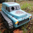
Step 1: Mk 1: Getting My Feet Wet!


The very first attempt was delightfully clever, because the whole construction was a single 3D print without any support or infill, it was also very not-clever because it was garbage and barely floated.
I really wanted to give it the cute “chibi” look that I associate with whoops, and of course I wanted to feature the my favorite "Goober" canopy as a design element, unfortunately it was simply too heavy and sat way too low in the water to work as an airboat.
I don’t even have any pictures of it on the water, presumably due to my disappointment, but the effort on Mk1 wasn’t wasted, because it proved to be a great platform to get the differential thrust mix configured, and do a bit of preliminary tuning. The little airboat actually ran rather nicely on hard smooth flooring and was fun to drive, if a little loud!
Step 2: Mk 2: Wood It Work?


Mk1 proved to be a bit too dense, so I decided to go old-school and carve a basic hull out of a block of Balsa wood, which was rather satisfying and extremely easy to do with nothing more than a hand saw and sand paper.

Since Balsa sucks up water like a sponge I gave it a good few coats of acrylic craft paint to seal it.
The next step was to create a self contained “thrust pod” which holds the flight controller, two motors, goober canopy and 1s battery, all in one handy little package that can be easily moved around between hulls. This proved to be a smart solution, and was used well past the Balsa stage.

The thrust pod is attached to the wood base with a few M2 screws. Access to the FC for tuning was a nuisance though, since it had to be removed to access the USB port.
The float test in a bucket looked great!

You can see in the pictures below that I added a raised bow to (try) prevent nose-diving.
This was… partially successful at best. The entire weight distribution of the boat is completely wrong, resulting in something that desperately wanted to flip on its face. As soon as the nose or front corner catches the water it becomes a pivot point and the props lift the rear, causing a disastrous cartwheel that tests the waterproofing to it’s limit!
The steering however does work well, and the boat scoots along with impressive pace while it is upright. Onwards to Mk 3!
Step 3: Mk 3 & Mk 4: Water Time to Be Alive!


In the previous step we made some progress towards a working airboat but the short flat balsa hull was prone to flipping right on it’s face with any sudden stops. One of the biggest annoyances with FPV drones is having to put down your goggles and do the walk of shame when you can’t fly out of a crash, I can guarantee you, the swim of shame is worse! 😂
The main reason I chose an airboat in the first place was that it would be the least likely to get tangled and stuck, but capsizing is equally problematic and needs to be fixed. Back to the drawing board then, I designed a longer hull with a raised prow, to prevent it nose-diving. You can see similar shapes on some full-scale airboats. The boat is also designed with a flat rear, which is convenient for printing, and I made sure that none of the angles resulted in more than 45 degrees of overhang when printing This hull accepted the same “thrust pod” from the previous boat, so that I didn’t have to move any electronics around. Making sure that your components are modular and re-usable is a huge benefit when experimenting and iterating towards a goal.
Watertight 3D Prints

Note, the model is solid, so you can balance hull strength and weight by adjusting print settings.
The images above show how the slicer is used to make the hull hollow, by printing without any support or infill, and only two perimeter walls, we get a relatively lightweight and robust result. Ensuring that the hull is watertight can be tricky with thin-wall prints, but there are a few things you can do to help
- Print hotter (to ensure good bonding between layers)
- Print slower (for layer bonding too)
- Over-extrude slightly (I used about 5%)
In the end my PETG print had two pinprick holes which I fixed with superglue, but an alternative solution would be to paint/varnish the whole thing.
Testing - Mk3
This iteration was the first to be able to reliably putter around a pond without getting stuck or capsizing, which is definitely a minor win in boat-building… but it never was able to get up to and significant speed since it has way too much drag, and the weight was too far forward. I believe the thrust of the motors, being so high above the water-line relative to the short hull, was creating a pitching moment forwards, preventing the nose from coming up on to a plane.
Step 4: Mk 5: Back to the Drawing Board!


I've learned a lot through the previous iterations, namely:
- The FC USB port needs to be accessible, so we are keeping the "removable pod" design
- The motors need to be as low as possible (without striking water)
- The motors can be tilted down (but only 1 or 2 degrees). This is so that the thrust is directly forwards when the bow lifts up.
- Don't skimp on hull volume, we need that buoyancy!
I also surmised a few things, which I included in this design
- Tried to remove sharp corners from the front of the hull, so that rolling and turning don't suddenly change the water resistance, which I imagine would make yaw harder for the FC to handle.
- Added a center channel, this should lower water resistance and aid stability, but it was primarily to reduce the surface area when running on hard ground.
Along with these I added some "nice to have"
- The battery slot is raised in the channel, so that the battery won't sit in water.
- Channels in the motor supports to hide the motor wires.
- Lots of curves and fillets, to make it easier on the eyeballs!
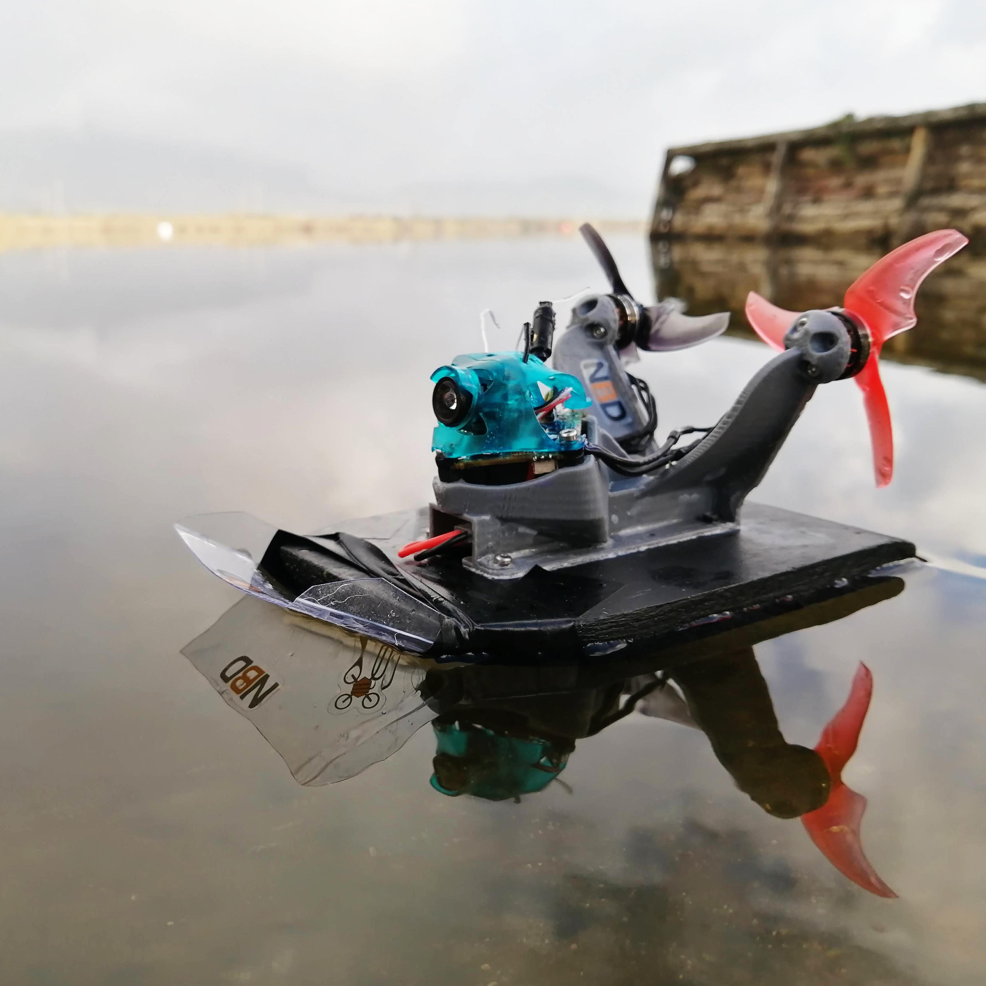
Step 5: Mk 5: the Print


Spoiler Warning: Mk 5 worked pretty decently, so it is the version I am releasing, here begins the build guide :-)
3D Printing
The procedure here is the same as in Step 3, so you can refer to that for details. The print is extremely simple though:
- Print the hull, vertically on its stern
- I used PETG (PLA will be fine, ABS might be tricky to make watertight)
- I used two perimeter walls with a 0.4mm nozzle
- Zero infill
- No support
- Print the thrust pod, vertically on it's rear
- I used PETG (Anything should be fine)
- It is a very thin design, so infill is mostly irrelevant, I'd recommend 3 perimeters.
- No support
Step 6: Mk 5: Assembly


Motors
The motors I used are a pair or 1202 8000kv motors, but you can try anything with the correct hole spacing (4xM2 on a 9mm diameter circle), such as these GEPRC motors.
You will probably need to extend the motor wires. Mount the motors to the thrust pod using M2x4 screws and figure out how long the wires need to be to get back to the FC.
Flight Controller
The FC and canopy are all attached using M2x8 screws, which thread directly into the plastic of the 3D print.
You'll need to use some rubber FC gummies to hold the FC PCB in place, and put the goober canopy on top of that.
Before you do any of this assembly though, make sure you have done your waterproofing, and then go back and make sure again! The water will get in everywhere.
I soldered the motor wires on to the PCB before it was mounted, but you can do it either way, if the props are removed the motors will pass through the hole in the pod, allowing you to mount/unmount them without desoldering.
Step 7: Mk 5: Betaflight Configuration, Differential Thrust


Differential thrust with two motors is a fun, simple and versatile way to make use of just two ESC channels to drive a land or water vehicle (or potentially a simple aircraft, but we’re not tackling that here). The combined thrust from both motors is used to push the vehicle forwards (or backwards) while the difference between the two is used for steering. It is an awesome use of an FC with one damaged ESC channel.
There are a few ways to tackle this, but the neatest is via a custom motor mix in the flight control firmware. The following explains how I achieved this on the BeeBrainBL FCs with BetaFlight 4.2.2 for my airboat project, but should be easily adaptable to any other firmware or FC.
Motor Numbering, what is connected where?
Before you can do anything you need to map the motors to the correct resource, and before you can do that you need to determine which motor is which (assuming you have soldered two motors to the FC)
- Connect to your FC in to Betaflight and go to the “Motors” tab
- Click on the “I Understand The Risks” button (assuming you do) and spin each motor up individually using the sliders (you'll need a battery connected)
- Record which motor number corresponds the left-hand motor, and which to the right. Assuming there are only two motors connected there will be two channels that do nothing in a default quad-x config.
- Got to the CLI tab and type “resource” and press enter to display the resource mapping. Look for the lines that show “resource MOTOR X YYY”, which define which motor (X) is mapped to which FC resource (YYY).
- You now know which motor numbers your left and right motors are on, and can record which resource/pin those are
- We can go ahead and define a custom mix and map the right motors to the right pins.
Assign Resources
The motor mix makes reference to motor/esc numbers, but your flight controller needs to know which pins talk to which motor, we do this with "resource mapping" in the Betaflight CLI.
The following is the example of the commands used on a v1 BBL with the motors on the two rear ESCs.
resource MOTOR 1 B06
resource MOTOR 2 B09
save
Motor Mixing Intro
The custom mix is set up via the CLI in betaflight, using the “mmix” command, which is of the form:
mmix n THROTTLE ROLL PITCH YAW
- n defines the motor number, indexed from zero
- THROTTLE (from 0.0 to 1.0)
- ROLL (-1.0 to 1.0)
- PITCH (-1.0 to 1.0)
- YAW (1.0 = Counter-clockwise / -1.0 = Clockwise)
The following series of commands is therefore used to set up a simple differential thrust mix on two motors, which both respond to throttle and yaw only.
mixer custom            #enable custom mix
mmix reset              #clear existing custom mix
mmix 0 1.0, 0, 0, -1.0  #left-hand motor
mmix 1 1.0, 0, 0,  1.0  #right-hand motor
save
Custom Mix Configuration and Testing
Now return to the “Configuration” tab and select “custom” under mixing, to enable our mix, as well as enabling "3D" so that the motors can be reversed. Remember that you will need to do this on the ESCs too, in the case of the NewBeeDrone BeeBrain this is done with JESC configurator.


Step 8: Mk 5: PID Tuning and Rates


PID tuning is an in-depth field, and definitely out of the scope of this Instructable to go into in great detail. I also don't consider myself an expert in it, so I'd be interested to have the pros out there weigh in on this.
Nevertheless, we need to change the PID tune quite dramatically in order to get a firmware designed to control a quadcopter to manage a boat's stability instead.
Fortunately we have only one axis to deal with, yaw (turning), since pitch and roll are out of our control, so this is actually quite a good project (at least on hard ground where things are predictable), to learn tuning fundamentals.
Head on over to the PID page of Betaflight and try starting with the following values for yaw. It doesn't matter what you have in Roll and Pitch since they aren't used in our custom mix at all.
This boat has a lot of yaw authority compared to a quadcopter, so it makes sense to me that we have to tune the PIDs way down.

Rates are really all down to personal preference, but I got rid of most of the expo/super rate, since the boat was already prone to "snapping" on turns as soon as the edge dug in, I also reduced the rates dramatically, since 300deg/s seemed more than enough for a surface vehicle, but experiment and see what you like!

Step 9: Wrapping Up

Well, I hope you had as much fun on that journey as I did! If you decide, against all better judgment, to risk your electronics by building one too then please do let me know how it went! (I'd love your vote in the Make It Move contest too!)
You can find and tag me on all the usual places, as well as follow along with my future bad ideas!

Second Prize in the
Make it Move Challenge


