

Introduction: MicroFluidic Pumping System


The Challenge
Investigating biological processes often requires model systems that mimic naturally occurring physiological environments. Many animal models and cell lines have served as gold standard tools for biomedical researchers to investigate biological functions in laboratories. Yet, many vital bio-activities such as hormones production rely on fluid dynamics to propagate signalling molecules at the right place and time throughout the body. In investigating such long-range communication mechanisms, a need exist to precisely mimic and control physiological fluid environments in laboratory settings. As a result, many commercial pumping systems are now available:
Yet, commercial solutions come highly expensive and are difficult to customize based on application requirements. As a result, various low-cost open source solutions have recently emerged in the literature:
Although being low cost and easily customizable, open-source solutions lack an intuitive user interface allowing to easily adjust pumping parameters without modifying the underlying source code of the system.
Project Objectives / Scope
The present project aims to improve the design of the PiFlow system by designing a graphical user interface to be displayed on an LCD touch screen display to adjust flow rate parameters easily. Specifically, the interface will allow the user to select between three different modes. The static flow mode will allow setting a constant flow rate (uL/Min) to be executed for a pre-defined flow time (Sec). The dynamic flow mode will allow the user to select a range of flow rate values where the system will linearly adjust the pumping rate (uL/Min) following a pre-defined sweep rate (uL/Min) adjustable through the interface. Lastly, for applications requiring higher complexity, a custom mode will allow the upload of a CSV file containing a list of flow rate parameters to be executed by the system. The underlying code of the interface will be made available for modification and improvement on the Github Project Page. Overall, the interface serves as a first design iteration utilizable in various microfluidic open source systems.
Attachments

Supplies

Mechanical Components
- 3D Printing Filament - PLA Plastic
- 3D Printer - Creality Ender 3
- Clear Plastic Glue
Electronic Components
- 1x Raspberry Pi 3 Model B
- 2x High Pump Driver (Best for high flow rate application - Select the driver according to required flow rate)
- 2x Low Pump Driver (Best for low flow rate application - Select the driver according to required flow rate)
- 2x 0.1 uF Decoupling Capacitor
- 2x TMU Switch IC
- 2x Molex Connector
- Raspberry Pi Pin Connectors
- 1x 7'' LCD Screen
- 1x HDMI 90' Adapter
- 1x HDMI Extender Capble
Fluidic Components
Software & Manufacturing House
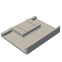
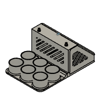
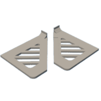
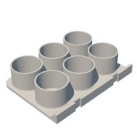
Step 1: Mechanical Design


Procedures
- Fusion 360 was utilized to design the components. The STL files provided below can be downloaded and uploaded directly into a 3D printer. Alternatively, the Fusion 360 Model can be downloaded from the Autodesk Gallery.
- The printing parameters selected according to standard recommendations for PLA material:
Bed Temperature --> 70C
Nozzle Temperature --> 220C
Flow Rate --> 90%
- Each component was assembled using Clear Plastic Glue which was found to be durable. Alternatively, the design can be modified to allow assembly with screws.
- Holes were drilled according to the Luer Tubing Adapter dimensions. Clear plastic glue was used to mount the adapters.
- The inner diameters of the bottle holders can be adjusted according to the size of the solution vessels utilized.


Step 2: Electronic Circuit


Electronic Components
- 1x Raspberry Pi 3 Model B
- 2x High Pump Driver (Best for high flow rate application - Select the driver according to required flow rate)
- 2x Low Pump Driver (Best for low flow rate application - Select the driver according to required flow rate)
- 2x Piezoelectric Pump
- 2x 0.1 uF Decoupling Capacitor
- 2x TMU Switch IC
- 2x Molex Connector
- Raspberry Pi Pin Connectors
- 1x 7'' LCD Screen
- 1x HDMI 90' Adapter
- 1x HDMI Extender Cable
Design Software & Manufacturing House
Procedures
- Upload each component into Eagle software. Snap EDA can be used to find part's libraries not already downloaded in Eagle. A tutorial can be found HERE.
- Create the circuit schematic by connecting each pin following the design provided in the above visuals. Alternatively, the schematic file is provided below. Eagle design tutorials can be found HERE.
- Design the PCB layout using Fusion 360. First, generate a PCB design file in Eagle from the produced schematic and upload the PCB layout from Fusion 360. A tutorial can be found HERE.
- Route each connection onto the PCB layout. A tutorial can be found HERE.
- Delete any unwanted names and values on the surface layer of the PCB. Additional descriptive names or values can alternatively be added if needed. A tutorial can be found HERE.
- Generate the Gerber manufacturing files. Then, upload the zip file into the JLC PCB ordering page and enter the required information. More details about the ordering process can be found HERE.
- Order the required electronic components provided in the above list. Once received, solder each component onto the PCB following the design provided above. Next, insert the piezoelectric pumps into their respective Molex connectors.
- Alternatively, the overall procedures reported in the PiFlow project can be followed. However, the present circuit slightly differs in utilizing a different Raspberry Pi model as well as relying on switch IC to turn the driver ON/OFF.
NOTE: The Gerber manufacturing files paired with the Eagle design files can be downloaded from the GitHub Project Page.
Step 3: Software Interface


Software Tools
Procedures
- Download the software dependencies onto the Raspberry Pi microcontroller following the commands below:
sudo apt-get update
sudo apt-get dist-upgrade
sudo apt-get install qt5-default
sudo apt-get install qtcreator
sudo apt-get install libqt5serialport5
sudo apt-get install libqt5serialport5-dev
sudo apt-get install qttools5-dev-tools
sudo apt-get install eric
sudo reboot
- Create your project directory environment in Eric IDE. Additionally, open QT-Designer to design the front-end layout of the interface. QT-Designer tutorials can be found HERE if needed.
NOTE: All codes can be downloaded from the GitHub Project Page.
Step 4: Calibration & Testing


Calibration & Testing
The calibration of the pumps was executed according to the procedures reported in the PiFlow project. The following features of the interface were tested as demonstrated in the videos provided:
- Selectable flow mode between static, dynamic, or custom.
- A pop-up warning message when out-of-range flow rate values are entered.
- A pop-up warning message when more than one flow mode is selected.
- A pop-up informative message when pumping execution is completed.
- Progress bar dynamically evolving to report pumping progress.
- OFF button allowing to reset the progress bar after execution.
Potential Improvements / Modifications
- A keypad pop-up window could be implemented to enter the parameters directly on the touch screen display to eliminate the need for a computer keyboard to enter the parameters.
- The size of the pop-up message remains to be scaled according to the size of LCD utilized.
- Although the OFF button currently reset the progress bar after each execution, the underlying OFF functions need to be improved to reset the execution parameters entered.
- The flowRate_conversion function converting flow rate values entered by the user to appropriate PWM frequencies should be optimized according to the model of pumps and drivers utilized. Different components require different driving frequencies to produce similar flow rates.
IMPORTANT --> The overall project is a first iteration design and requires many improvements. Please feel free to download the code from the GitHub Project Page and add additional features. Ensure to report your improvements. After all, open-source solutions can only be as optimized as the number of design improvements made by the community.


