

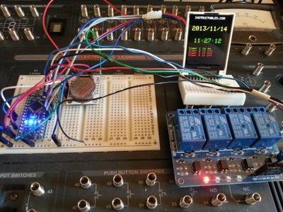
Introduction: Mini Arduino Multi Function Controller W/ LCD Display


This Instructable builds on the mini Arduino environment monitor and mini Arduino EEG monitor Instructables.
It allows you to control up to 4 relays using time, temperature and /or Light, your mind, or whatever sensor you would like to use.
The examples are prototypes, I don't go any further than putting them together on a breadboard. I haven't made a permanent case for them
The main purpose of this instructable is to demonstrate how you can use the arduino to control any device using sensor input and conditional logic to make decisions and activate the device.
My objectives are to make these instructables inexpensive, simple, practical, and interesting.
Step 1: Parts and Components


For the Timer control:
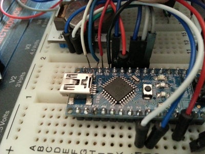
1. Arduino, I think anyone will do, but I'm using a Sainsmart nano clone.
2. A RTC module for Arduino
3. A Sainsmart 4 Relay module
4 A Sainsmart 1.8" LCD Color display
5. Jumper wires
6. A mini breadboard to hold the display and/or a larger breadboard for the nano and RTC (I used my RS electronic learning lab)
For the Brain Controller:
- An Arduino
- A Sainsmart 4 Relay module
- A Sainsmart 1.8" LCD Color display
- A hacked MindfLEX headset
- An Arduino
- A Sainsmart 4 Relay module
- A Sainsmart 1.8" LCD Color display
- A DHT11 or similar temperature sensor, or a thermistor
- a CDS light sensor
Step 2: Timer Controlled Relays
So Let's start with the Timer controller:
This example allows you to control the relays with data provided by the RTC. you can use the date and time data to turn on and/or off the relays.
There are many instructables that show you how to do just that, but this one provides you feedback status using the color LCD display.
You will need to have the Mini Arduino Enviroment monitor with RTC built to start this project. We will add the 4 Relay module.
Step 3: Connect Relay Module to Arduino
I used a connector salvaged from a PC Audio input to do the connections.
Don't forget you also need to have the RTC module and the Color LCD display connected.
LCD DISPLAY CONNECTIONS
- VCC connected to Arduino VCC (or external 6v power source)
- GND connected to GND
- SCL connected to digital PIN 4
- SDA connected to digital PIN 5
- CS connected to digital PIN 6
- PS/DC connected to digital PIN 7
- RES connected to digital PIN 8
RTC CONNECTIONS
Connect the RTC VCC to the Arduino VCC(or external 6v power source)
RTC GND to the Arduino GND
RTC SDA to the Arduino Analog Pin 4
RTC SCL to the Arduino Analog Pin 5
RELAY MODULE CONNECTIONS
- Connect RELAY GND to Arduino GND
- Connect RELAY VCC to Arduino VCC(or external 6v power source)
- Connect RELAY IN1 to ArduinoPIN 9
- Connect RELAY IN2 to Arduino PIN 10
- Connect RELAY IN3 to Arduino PIN 11
- Connect RELAY IN4 to Arduino PIN 12
Step 4: Notes Before Loading the Timer Controlled Sketch

- Make sure you have all the connections to the display, the RTC module, and the Relay module wired correctly.
- Make sure yo have all the libraries needed installed, refer to My Mini Arduino environment monitor instructable for a more detailed explanation of what you need.
- You may want to use an external 6v power source to avoid overloading the USB Port
- The sketch is just an example that turns the relays on and of in a one minute cycle, you can change the code to suit your requirements.
- Don't be afraid to experiment and change the code! For example, can you change the code tor turn on a relay for 5 minutes at 6 am? Or set the timer to activate the relays on your birthday?
Step 5: The Code FOR TIMER CONTROL
// Sketch Build 1.04 compiled on Arduino 1.0.3.
// This sketch uses the RTC to control 4 relays at whatever cycle or time interval you wish.
// copy the sketch below and paste it into the Arduino IDE verify, and run the program.
// this sketch was created using code from the adafruit and RTC -libraries
//RTC CONNECTIONS
//Connect the RTC VCC to the Arduino +5 v
// RTC GND to the Arduino GND
// RTC SDA to the Arduino Analog Pin 4
// RTC SCL to the Arduino Analog Pin 5
// LCD DISPLAY CONNECTION
#define sclk 4 //connected to digital PIN 4
#define mosi 5 //connected to digital PIN 5
#define cs 6 //connected to digital PIN 6
#define dc 7 //connected to digital PIN 7
#define rst 8 //connected to digital PIN 8
// RELAY CONNECTION
// GND connected to Arduino GND
int Pin1 = 9; // IN1 connected to digital 9
int Pin2 = 10; // IN2 connected to digital 10
int Pin3 = 11; // IN3 connected to digital 11
int Pin4 = 12; // IN4 connected to digital 12
// VCC connected to Arduino +5v
#include // Core graphics library
#include // Hardware-specific library
#include // library needed for RTC
#include // library needed for RTC
#include "RTClib.h" //RTC Library
RTC_DS1307 RTC;
Adafruit_ST7735 tft = Adafruit_ST7735(cs, dc, mosi, sclk, rst);
void setup(void) {
// DEFINING PINS FOR RELAY CONTROL
pinMode(Pin1, OUTPUT);
pinMode(Pin2, OUTPUT);
pinMode(Pin3, OUTPUT);
pinMode(Pin4, OUTPUT);
Wire.begin();
RTC.begin();
tft.initR(INITR_BLACKTAB); // initialize a ST7735S chip, black tab
tft.fillScreen(ST7735_BLACK); // Clear screen
digitalWrite(Pin1, 1 );
digitalWrite(Pin2, 1 );
digitalWrite(Pin3, 1 );
digitalWrite(Pin4, 1 );
tft.setCursor(0,50);
tft.println(" Waiting 10 seconds ");
tft.println(" for RTC to Sync ");
delay(10000);//wait for RTC to Respond, if not set time
tft.fillScreen(ST7735_BLACK); // Clear screen
if (! RTC.isrunning()) {
tft.println(" RTC was NOT running!");
tft.println(" Resetting RTC ");
// following line sets the RTC to the date & time this sketch was compiled
RTC.adjust(DateTime(__DATE__, __TIME__));
tft.fillScreen(ST7735_BLACK); // Clear screen
}
}
void loop() {
tft.setCursor(10,10);
tft.setTextColor(ST7735_WHITE);
tft.setTextSize(1);
tft.println("TIMER CONTROL");
tft.setTextColor(ST7735_YELLOW,ST7735_BLACK);//set text color & size for DATE coming from TinyRTC
tft.setTextSize(2);
tft.setCursor(5,30);
DateTime now = RTC.now(); //GRAB DATE AND TIME FROM RTC
tft.print(now.year(), DEC);
tft.print('/');
tft.print(now.month(), DEC);
tft.print('/');
tft.print(now.day(), DEC);
tft.println(' ');
tft.setCursor(15,70);
tft.setTextColor(ST7735_GREEN,ST7735_BLACK); //set color for TIME
tft.setTextSize(2);//set text size for TIME coming from TinyRTC
tft.print(now.hour(), DEC);
tft.print(':');
if(now.minute() < 10) { //PRINT A 0 IN FRONT OF THE MINUTE IF LESS THAN 10
tft.print('0');
tft.print(now.minute(), DEC);
}
else {
tft.print(now.minute(), DEC);
}
tft.print(':');
if(now.second() < 10) {//PRINT A 0 IN FRONT OF THE SECONDS IF LESS THAN 10
tft.print('0');
tft.print(now.second(), DEC);
}
else {
tft.print(now.second(), DEC);
}
tft.println(" ");
// THIS IS THE DECISION MAKING PORTION OF THE SKETCH, THIS EXAMPLE IS A ONE MINUTE CYCLE
// FOR DEMO PURPOSES: IT TURNS ON RELAY 1 AT 10 SECONDS, THEN OFF AT 20
// IT THEN TURNS RELAY 2 AND 4 ON AT 40 SECONDS AND OFF AT 50,
// AT 50 SECONDS IT TURNS ON RELAY 1 AND 3 THEN OFF AT 0
if(now.second() == 10) {
tft.setCursor(0,100);
tft.setTextColor(ST7735_GREEN,ST7735_BLACK); //set color for TIME ON
tft.setTextSize(1);//set text size
tft.print("Relay 1 is on ");
digitalWrite(Pin1, 0);
}
if(now.second()== 20) {
tft.setCursor(0,100);
tft.setTextColor(ST7735_RED,ST7735_BLACK); //set color for TIME ON
tft.setTextSize(1);//set text size
tft.print("Relay 1 is off ");
digitalWrite(Pin1, 1);
}
if(now.second()== 40){
digitalWrite(Pin1, LOW);
digitalWrite(Pin2, HIGH);
digitalWrite(Pin3, LOW);
digitalWrite(Pin4, HIGH);
tft.setCursor(0,100);
tft.setTextColor(ST7735_RED,ST7735_BLACK); //set color for TIME ON
tft.setTextSize(1);//set text size
tft.setTextColor(ST7735_GREEN,ST7735_BLACK);
tft.println("Relay 1 is on ");
tft.setTextColor(ST7735_RED,ST7735_BLACK);
tft.println("Relay 2 is off ");
tft.setTextColor(ST7735_GREEN,ST7735_BLACK);
tft.println("Relay 3 is on ");
tft.setTextColor(ST7735_RED,ST7735_BLACK);
tft.println("Relay 4 is off ");
}
if(now.second()== 50){
digitalWrite(Pin1, HIGH);
digitalWrite(Pin2, LOW);
digitalWrite(Pin3, HIGH);
digitalWrite(Pin4, LOW);
tft.setCursor(0,100);
tft.setTextColor(ST7735_RED,ST7735_BLACK); //set color for TIME ON
tft.setTextSize(1);//set text size
tft.println("Relay 1 is off ");
tft.setTextColor(ST7735_GREEN,ST7735_BLACK);
tft.println("Relay 2 is on ");
tft.setTextColor(ST7735_RED,ST7735_BLACK);
tft.println("Relay 3 is off ");
tft.setTextColor(ST7735_GREEN,ST7735_BLACK);
tft.println("Relay 4 is on ");
}
if(now.second()== 00){
digitalWrite(Pin1, HIGH);
digitalWrite(Pin2, HIGH);
digitalWrite(Pin3, HIGH);
digitalWrite(Pin4, HIGH);
tft.setCursor(0,100);
tft.setTextColor(ST7735_RED,ST7735_BLACK); //set color for TIME ON
tft.setTextSize(1);//set text size
tft.println("Relay 1 is off ");
tft.println("Relay 2 is off ");
tft.println("Relay 3 is off ");
tft.println("Relay 4 is off ");
}
}
Step 6: Video of the Timer Controller Working
Step 7: Timer Controlled Bonus: Instrumentation Sterilizer and Hot /cold Plate Idea


As a practical example for use of the timer in a lab environment, you can use the timer to control a UV light in an enclosed casing to sterilize medical instruments such as dental picks, or surgical tools. I used the UV light from a broken toothbrush sterilizer (the electronic control stopped working) . I used a 12v to high voltage source from an automotive EL circuit to power the UV light bulb.
Another example is to use the peltier element driven, Thermoelectric Heating/Cooling unit salvaged from an old cooler I had to use as a hot cold plate.
Use the relays to control the power, and modify the program to suite your needs!
Step 8: Brain Controlled Relays
This example allows you to control the relays with data provided by the hacked MindFlex Headset. The program monitors three signals coming from the headset: the signal quality, the attention, and the meditation. I suggest you look at my EEG Monitor instructable before you start this example, as it explains how to hack the MindFlex headset for use with the Arduino, and how to interpret the data coming from the headset.
I am using the Signal quality data to control relay 1, the attention data to control relay 2, and the meditation data to control relay 3. Relay 4 is not used in this example.
Relay 1 turns on if the signal quality is = to 0 (0 is maximum signal strength 200 is no signal)
Relay 2 turns on if the attention is > 50 (100 is maximum attention 0 is minimum attention)
Relay 3 turns on if the meditation is > 50 (100 is maximum meditation 0 is minimum meditation)
As with the timer control , you can adjust these values to suit. Your needs.
Step 9: Sketch to Control the Relays With Your Mind
// Sketch Build compiled on Arduino 1.0.3.
// This sketch was modified to run the loop faster.. refresh rate is about 1.5 seconds.
// copy the sketch below and paste it into the Arduino IDE verify, and run the program.
// this sketch was created using code from the adafruit and brain-libraries
#define sclk 4
#define mosi 5
#define cs 6
#define dc 7
#define rst 8
// GND connected to Arduino GND
int Pin1 = 9; // IN1 connected to digital 9
int Pin2 = 10; // IN2 connected to digital 10
int Pin3 = 11; // IN3 connected to digital 11
int Pin4 = 12; // IN4 connected to digital 12
// VCC connected to Arduino +5v
#include <Adafruit_GFX.h> // Core graphics library
#include <Adafruit_ST7735.h> // Hardware-specific library
#include <SPI.h>
#include <Brain.h>
Adafruit_ST7735 tft = Adafruit_ST7735(cs, dc, mosi, sclk, rst);
Brain brain(Serial);
void setup(void) {
tft.initR(INITR_BLACKTAB); // initialize a ST7735S chip, black tab
pinMode(Pin1, OUTPUT);
pinMode(Pin2, OUTPUT);
pinMode(Pin3, OUTPUT);
pinMode(Pin4, OUTPUT);
digitalWrite(Pin1, 1 );
digitalWrite(Pin2, 1 );
digitalWrite(Pin3, 1 );
digitalWrite(Pin4, 1 );
tftPrintTest(); //Initial introduction text,
delay(1000);
tft.fillScreen(ST7735_BLACK); // clear screen
tft.setTextColor(ST7735_WHITE);
tft.setTextSize(1);
tft.setCursor(30,0);
tft.println("Brain Control");
Serial.begin(9600);
}
void loop() {
if (brain.update()) {
if (brain.readSignalQuality() > 199) {
tft.fillScreen(ST7735_BLACK);
tft.setCursor(10,60);
tft.setTextSize(1);
tft.setTextColor(ST7735_RED,ST7735_BLACK);
tft.println("SQ low");
tft.fillScreen(ST7735_BLACK);
}
else {
tft.setCursor(30,0);
tft.setTextSize(1);
tft.println("Brain Control");
tft.drawLine(0, 20, tft.width()-1, 20, ST7735_WHITE);
tft.drawLine(0, 130, tft.width()-1, 130, ST7735_WHITE);
tft.setCursor(0, 30);
tft.setTextColor(ST7735_YELLOW,ST7735_BLACK);
tft.setTextSize(1);
tft.print(" signal quality :");
tft.print(brain.readSignalQuality());
tft.println(" ");
tft.println(" ");
tft.setTextColor(ST7735_GREEN,ST7735_BLACK);
tft.println(" Attention :");
tft.setTextSize(2);
tft.setCursor(60, 60);
tft.print(brain.readAttention());
tft.println(" ");
tft.setTextColor(ST7735_WHITE,ST7735_BLACK);
tft.setTextSize(1);
tft.println(" ");
tft.print(" Meditation :");
tft.setTextSize(2);
tft.setCursor(60, 100);
tft.print(brain.readMeditation());
tft.println(" ");
if(brain.readSignalQuality() == 0) {
tft.setCursor(0,140);
tft.setTextColor(ST7735_GREEN,ST7735_BLACK); //set color for TIME ON
tft.setTextSize(1);//set text size
tft.print(" Relay 1 is on ");
digitalWrite(Pin1, 0);
}
else {
tft.setCursor(0,140);
tft.setTextColor(ST7735_RED,ST7735_BLACK); //set color for TIME OFF
tft.setTextSize(1);//set text size
tft.print(" Relay 1 is off ");
digitalWrite(Pin1, 1);
}
}
if(brain.readAttention() > 50) {
tft.setCursor(0,75);
tft.setTextColor(ST7735_GREEN,ST7735_BLACK); //set color for TIME ON
tft.setTextSize(1);//set text size
tft.print(" Relay 2 is on ");
digitalWrite(Pin2, 0);
}
else {
tft.setCursor(0,75);
tft.setTextColor(ST7735_RED,ST7735_BLACK); //set color for TIME OFF
tft.setTextSize(1);//set text size
tft.print(" Relay 2 is off ");
digitalWrite(Pin2, 1);
}
if(brain.readMeditation() > 50) {
tft.setCursor(0,118);
tft.setTextColor(ST7735_GREEN,ST7735_BLACK); //set color for TIME ON
tft.setTextSize(1);//set text size
tft.print(" Relay 3 is on ");
digitalWrite(Pin3, 0);
}
else {
tft.setCursor(0,118);
tft.setTextColor(ST7735_RED,ST7735_BLACK); //set color for TIME OFF
tft.setTextSize(1);//set text size
tft.print(" Relay 3 is off ");
digitalWrite(Pin3, 1);
}}}
void tftPrintTest() {
tft.setTextWrap(false);
tft.fillScreen(ST7735_BLACK);
tft.setCursor(0, 10);
tft.setTextColor(ST7735_WHITE);
tft.setTextSize(1);
tft.println(" INSTRUCTABLES.COM");
delay(500);
tft.setCursor(30, 60);
tft.setTextColor(ST7735_RED);
tft.setTextSize(2);
tft.println("Brain");
tft.setTextColor(ST7735_YELLOW);
tft.setCursor(5, 80);
tft.println("Controler ");
tft.setTextColor(ST7735_BLUE);
delay(50);
}
Step 10: Video of Mind Controlled Relays

Step 11: Bonus: Mind Controlled LASER Light Show


This example shows you how control a LASER and two motors with the MindFlex head set. You will not need the Relay module. The example shows how to control the speed of the motors using PWM from the data coming from the Headset. I am using the Attention and meditation signals to control the motors, and the signal Quality to turn the laser on and off.
To build this example, uou need the LASER Light show module, which I got in the Target clearance rack after Halloween, but you can also use two motors from an old PC CD Player and a laser from a cheap laser pointer.
Connect Laser - to pin 9
Connect motor 1 - to pin 10
Connect motor 2 - to pin 11
Connect all + Red wires to Arduino VCC or +6v power
Step 12: Mind Controlled Laser Light Show Code
// Sketch Build compiled on Arduino 1.0.3.
// copy the sketch below and paste it into the Arduino IDE verify, and run the program.
// this sketch was created using code from the adafruit and brain-libraries
#define sclk 4
#define mosi 5
#define cs 6
#define dc 7
#define rst 8
// GND connected to Arduino GND
int Pin1 = 9; // IN1 connected to digital 9 conected to laser -
int Pin2 = 10; // IN2 connected to digital 10 connected to motor 2 -
int Pin3 = 11; // IN3 connected to digital 11 connected to motor 1 -
int Pin4 = 12; // IN4 connected to digital 12 not used here
// motor 1 & 2 + , and laser + connect to Arduino +5v
#include <Adafruit_GFX.h> // Core graphics library
#include <Adafruit_ST7735.h> // Hardware-specific library
#include <SPI.h>
#include <Brain.h>
Adafruit_ST7735 tft = Adafruit_ST7735(cs, dc, mosi, sclk, rst);
Brain brain(Serial);
void setup(void) {
tft.initR(INITR_BLACKTAB); // initialize a ST7735S chip, black tab
pinMode(Pin1, OUTPUT);
pinMode(Pin2, OUTPUT);
pinMode(Pin3, OUTPUT);
pinMode(Pin4, OUTPUT);
digitalWrite(Pin1, 1 );
digitalWrite(Pin2, 1 );
digitalWrite(Pin3, 1 );
digitalWrite(Pin4, 1 );
tftPrintTest(); //Initial introduction text,
delay(1000);
tft.fillScreen(ST7735_BLACK); // clear screen
tft.setTextColor(ST7735_WHITE);
tft.setTextSize(1);
tft.setCursor(30,0);
tft.println("Brain Control");
Serial.begin(9600);
}
void loop() {
if (brain.update()) {
if (brain.readSignalQuality() > 199) {
tft.fillScreen(ST7735_BLACK);
tft.setCursor(10,60);
tft.setTextSize(1);
tft.setTextColor(ST7735_RED,ST7735_BLACK);
tft.println("SQ low");
tft.fillScreen(ST7735_BLACK);
}
else {
tft.setCursor(30,0);
tft.setTextSize(1);
tft.println("Brain Control");
tft.drawLine(0, 20, tft.width()-1, 20, ST7735_WHITE);
tft.drawLine(0, 130, tft.width()-1, 130, ST7735_WHITE);
tft.setCursor(0, 30);
tft.setTextColor(ST7735_YELLOW,ST7735_BLACK);
tft.setTextSize(1);
tft.print(" signal quality :");
tft.print(brain.readSignalQuality());
tft.println(" ");
tft.println(" ");
tft.setTextColor(ST7735_CYAN,ST7735_BLACK);
tft.println(" Attention :");
tft.setTextSize(2);
tft.setCursor(60, 60);
tft.print(brain.readAttention());
tft.println(" ");
tft.setTextColor(ST7735_WHITE,ST7735_BLACK);
tft.setTextSize(1);
tft.println(" ");
tft.print(" Meditation :");
tft.setTextSize(2);
tft.setCursor(60, 100);
tft.print(brain.readMeditation());
tft.println(" ");
if(brain.readSignalQuality() == 0) {
tft.setCursor(0,140);
tft.setTextColor(ST7735_GREEN,ST7735_BLACK); //set color for TIME ON
tft.setTextSize(1);//set text size
tft.print(" LASER is on ");
digitalWrite(Pin1, 0);
}
else {
tft.setCursor(0,140);
tft.setTextColor(ST7735_RED,ST7735_BLACK); //set color for TIME ON
tft.setTextSize(1);//set text size
tft.print(" LASER is off ");
digitalWrite(Pin1, 1);
}
}
if(brain.readAttention() > 5) {
tft.setCursor(0,75);
tft.setTextColor(ST7735_GREEN,ST7735_BLACK); //set color for TIME ON
tft.setTextSize(1);//set text size
tft.print(" MOTOR 2 is ON ");
analogWrite(Pin2, brain.readAttention());
}
else {
tft.setCursor(0,75);
tft.setTextColor(ST7735_RED,ST7735_BLACK); //set color for TIME ON
tft.setTextSize(1);//set text size
tft.print(" MOTOR 2 is OFF ");
digitalWrite(Pin2, 1);
}
if(brain.readMeditation() > 5) {
tft.setCursor(0,118);
tft.setTextColor(ST7735_GREEN,ST7735_BLACK); //set color for TIME ON
tft.setTextSize(1);//set text size
tft.print(" MOTOR 1 is ON ");
analogWrite(Pin3, brain.readMeditation());
}
else {
tft.setCursor(0,118);
tft.setTextColor(ST7735_RED,ST7735_BLACK); //set color for TIME ON
tft.setTextSize(1);//set text size
tft.print(" MOTOR 1 is OFF ");
digitalWrite(Pin3, 1);
}}}
void tftPrintTest() {
tft.setTextWrap(false);
tft.fillScreen(ST7735_BLACK);
tft.setCursor(0, 10);
tft.setTextColor(ST7735_WHITE);
tft.setTextSize(1);
tft.println(" INSTRUCTABLES.COM");
delay(500);
tft.setCursor(30, 60);
tft.setTextColor(ST7735_RED);
tft.setTextSize(2);
tft.println("Brain");
tft.setTextColor(ST7735_YELLOW);
tft.setCursor(5, 80);
tft.println("Controler ");
tft.setTextColor(ST7735_BLUE);
delay(50);
}
Step 13: Video of the Mind Controlled Laser Light Show
Step 14: Light And/or Temperature Controlled Relays Challenge
OK, now it's your turn to try to control the relays using light, and temperature! see if you can build a circuit and write the code. To do it, reference my other instructables, the information to do it is all there! If you can't figure it out, I will update this section with the steps needed. Good luck!
Step 15: Manual /Automatic Power Outlet Extension for Use With Relays


What you will need:
- A plastic electrical outlet box
- An outlet
- A power plug salvaged from an old PC power supply
- A rocker switch with reset can be salvaged from old power strip
- A PC power chord
- A two pin heavy duty male / female connector pair
- Electrical cable
- A heavy duty soldering iron and solder
- Wire cutter / stripper
- Utility knife or box cutter
- Screwdrivers
- Glue gun and glue sticks
Step 16: Outlet Construction


The construction is fairly straitforward; Use the utility knife or box cutter to cut out holes for the rocker switch, PC power plug, and two pin male plug, in the plastic electrical outlet box. Size the holes as best you can, and then insert the parts into the appropriate holes made. Secure the parts with glue, or screws, if possible. Use the pictures provided, to guide you and give you an idea of how to do this.
Once the parts are in place you need to wire the parts together and solder them in place.

Participated in the
Hardware Hacking

Participated in the
Make It Glow Contest

Participated in the
Build My Lab Contest


