

Introduction: Mini LED Lamp With Movement- (PIR) and Lightssensor (LDR)


Sexy title! I know.
This tutorial will teach you how to turn on 2 LEDs using a lights- and a motion sensor (PIR).
Useful, for when your power outlet is too far away/hidden in darkness or you just don't want to turn on too much light at night. Along with other imaginary purposes. Also in my country, a store-bought version cost at least 4 times as much as this one.
I have powered my devices with old nokia chargers.
Step 1: What to Buy / What You Need:
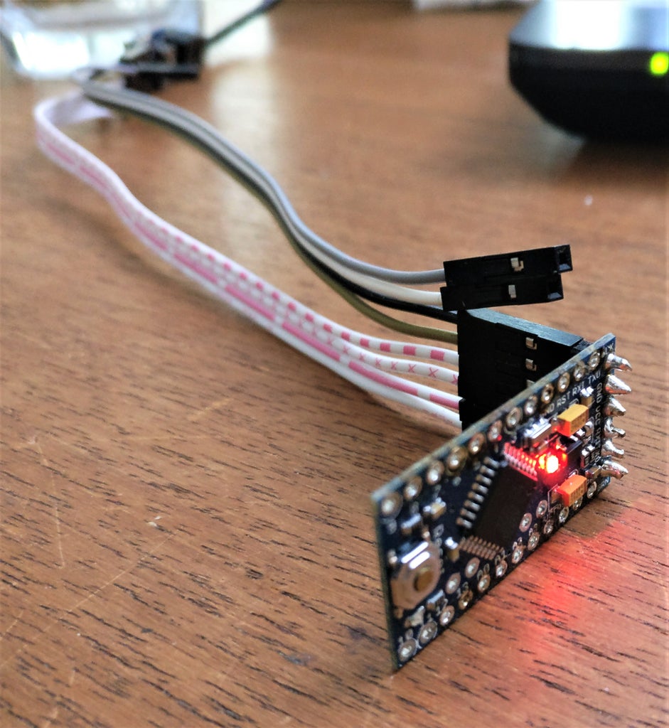
- Arduino mini pro x1
Ebay: Pro-Mini-Atmega328-5V-16MHz
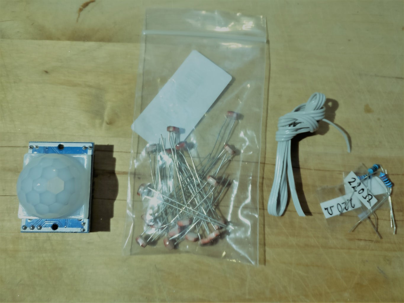
- LEDs x2
- PIR motion sensor x1
Ebay: Pyroelectric Infrared PIR Detector / Dealextreme: Pyroelectric Infrared PIR Motion Sensor
- 220 Ohm resistors x2
- 10k Ohm resistor x1
- Lightsensor / LDR x1
Ebay: 20PCS Photoresistor LDR CDS 5mm Light-Dependent Resistor Sensor GL5516 Arduino
*Links are for the hardware I use. Feel free to find equivalent substitutes.
Prerequisites/tools:
Soldering.
Insulation tubes or tape (Can be made without, if you dare!)
Pins / being able to upload to arduino mini
A small piece of wire - 2 cm
Pliers
Step 2: Upload Your Code
If you want . You can use my code. If you don't, go to step 3!
The code will basically turn the LEDs on if you walk in front of the sensor. Provided that its dark enough.
The sensor will only turn on its lights at night and not during the day. It has an upper and lower bound for when it will turn on. Hence, the arduino will turn off immediately if you turn on a lamp nearby and then on again when you turn off the lamp.
To find the sweet spot of when to turn on between night and day it calculates a running average of a minute for when its dark enough to turn on. It does this because the lightsensor gives very volatile/sensitive. If you didn't do it this way you might get the sensor to turn on and off and therefore blinking around your sweet spot.
When the arduino turns on the LEDs
The lights will be turned on for 5 seconds unless you turn on a light nearby.
Afterwards the light will be turned on for 6 seconds but will reset that period every time the arduino detects motion in front off it.
IE. The light will turn on for 11 seconds if you just walk by it at night.
In the beginning of the code I have made it easy to change the:
Lower threshold - When its light enough to turn off the LEDs
Upper threshold - When its definitely dark enough to turn on the LEDs
Average thresshold - When its dark enough to turn on the LEDs
Array [containing the fade to light] - change the last number to make the LEDs shine brighter or darker. IE. if the LEDs are too bright for your eyes at night.
The first break of 5 seconds
Second break of 6 seconds
Attachments

Step 3: Build It in the Right Order


If you want to make it as compact as my version where you place the PIR on top of the arduino board it's a good idea to start with soldering everything else before you solder the connection between the arduino board and the PIR sensor. Also confirm that you have a PIR that is connected the same way as mine. For reassurance check pictures with step 5.
If you want to power the device by other means go to step 4.
Firstly, solder the female power connector to the arduino.
I used old nokia phones to find my female connector. Just like the pictures.
I have done this before with great success. I had one old nokia phone where the female adapter could easily be removed by hand and just soldered on to the arduino.
For this build I had to modify the huge piece of plastic that the female connector on the old nokia phone was part of. It was way too big to solder on to the arduino board directly so I cut it up.
Step 4: Soldering


Just solder it like the pictures. I use insulation tubes just to be safe.
Solder a approximately 2 cm wire to the VCC with the 10 ohm resistor.
The first version I did was wired the same way but without the insulation tubes and even though the exposed metal comes close to short-circuiting the system it hasn't.
Step 5: Bend the Legs of the PIR


Now you might have a different PIR than the one I bought. To confirm the input/outputs of the legs of the PIR take off the plastic lid. For a thorough explanation of PIR check out https://www.instructables.com/id/PIR-Motion-Sensor-Tutorial/, it helped me.
The VCC leg needs to be bent down. We will connect it to the wire soldered on to the arduino board earlier.
The two other legs are bent a little curvy and then bent up again. This is to be able to fit the small arduino board between the capacitors on the PIR. The arduino board will be at an angle to the PIR but that is probably a good thing since you are likely to be installing this in some corner.
Step 6: Some More Soldering


Solder the wire from the arduino board to the VCC of the PIR.
To create the T intersection of wires in the picture you will need to solder some solid wire to the end of one leg of the LEDs and the lightsensor. You can just use the spare solid wire cut when the resistors was soldered on.
Finally solder the arduino board to the PIR. With the two legs from the PIR going to the d2 and Gnd of the arduino.
Step 7: Job Done!


Congrats, you did it!
Consider voting for me in one of the contest this is entered.
Step 8: Extra
The sweet spot:
When you buy cheap chinese products. There might be some differences between the individual parts. Also lightsensor comes in different types. Therefore you might want to measure the sweet spot you want by hooking up the light sensor to an arduino and read the value when its just about dark enough that you want your LEDs to light up.
You can find a way to do this following on of the basic arduino lesson attached.


Participated in the
Lights Contest 2017

Participated in the
Microcontroller Contest 2017


