

Introduction: Modules and Shields


In and of itself, the Arduino is limited to very basic input and output control. To do anything more requires building complex circuits out of many electronic components. Shield and modules are complex pre-built circuits designed to solve a particular task. This means that instead of building and connecting your Arduino to a big complicated homemade circuit, you can just attach it to the proper terminals on these boards, and they will do much of the work for you. This allows you to quickly and easily expand the functionality of the microcontroller without much fuss.
Step 1:

An Arduino shield is a special circuit board that plugs in on top of the Arduino and adds special functionality to it. It gets it's name because it is a little bit like the board is holding a shield in front of itself as protection.

People make all kinds of shields to enhance the capabilities of the Arduino. They are basically special circuits designed to do something very particular, and then attached directly to the Arduino. Given that there are an endless number of circuits that you can connect to the Arduino, there are also countless shields out in the world performing a wide variety of functions.
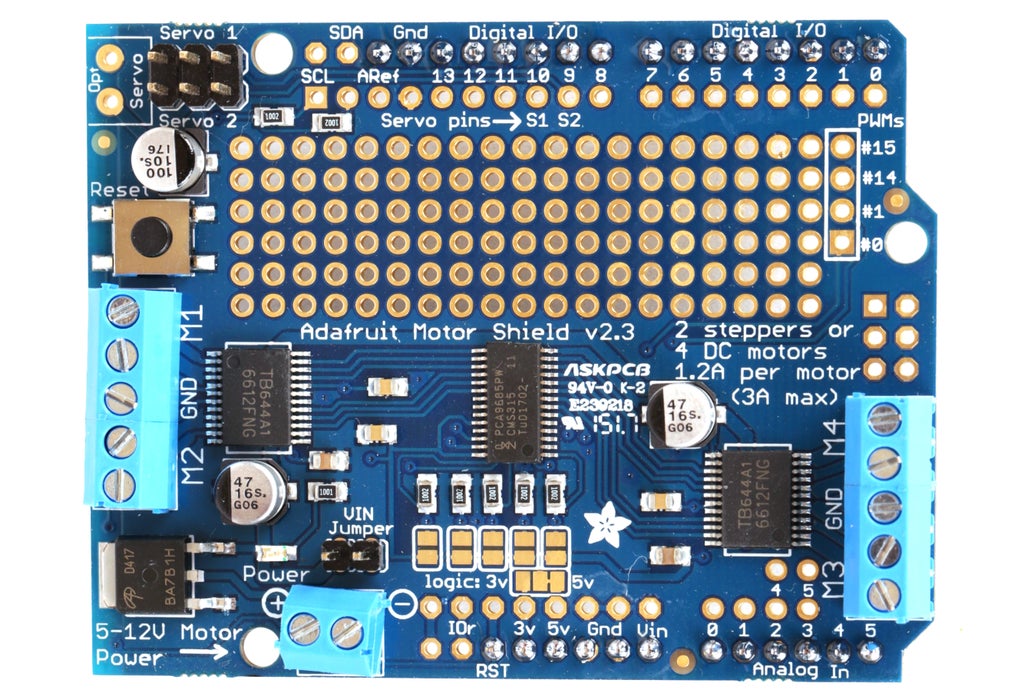
One of the most common types of shields encountered in hobby robotics is a motor shield. A motor shield is a circuit for controlling motors using one or more H-bridges, which — as discussed in the "Robot Brains" Lesson — is a special type of circuit that allows you to control motor direction (and, typically, speed as well). This shield has four separate H-bridges which allows you to control four different DC motors, or two stepper motors (or a combination thereof). The shield is also configured to provide a regulated (relatively) high-current power supply to two servo motors.

In this example I am using an Adafruit motor shield to simply control a single motor on Channel 1. To accomplish this I just wire a DC motor to the terminals labeled M1 and connect an external power supply (battery pack) to the power terminal block.
The benefit of using a shield is that you can connect it an external circuit board without messy wires. It fits squarely atop the Arduino
board, potentially saving space. It's also explicitly designed to work
with the Arduino, and often has a library associated with it.
Since shields tend to have fixed connections to the Arduino and a very specific functionality, they often have libraries associated with them. A library is a set of functions that you can call in your code that helps you perform common tasks quickly and easily. For instance, rather than writing complex Arduino code to interface with the hardware on this motor shield to turn on the motor, you can just install a library and use the motor "run" function.
This particular motor shield requires you to download and place the Adafruit Motor Shield V2 library in your software's library folder. If you are not sure how to install a library, check out the Arduino Class for more complete instructions.
Once it is installed, restart the Arduino software, and you will now see a sketch called "DCMotorTest" under File > Examples > Adafruit Motor Shield V2 Library. Open and run this sketch to see your motor in action.

However, there are tradeoffs to using shield as well. The downside is that it might tie up more pins on the Arduino than you need
by connecting unwanted functionality on the shield. Even if you don't plan to use all aspects of the shields, it nevertheless is always connecting those parts of the circuit to the Arduino. For
instance, we are controlling a single DC motor, but there are two pins hardwired to control servo motors that we are not using. This is less than ideal if we want to connect multiple other modules and components to the Arduino. Rarely can you stack different types of shields without these pins interfering.
An easy way to solve this problem is to use external modules and only connect the pins you need to the Arduino.
Step 2:

Modules, like shields, are boards that connect to an Arduino, and add special functionality. The difference with modules is that they are not Arduino-specific. They do not need to plug over top of the Arduino, but can be connected to a number of different controller boards using hookup wire, or sometimes can even run as a stand-alone device (i.e. all by themselves).

The IR motion sensor and the Ping sensor we used in the previous sensor lesson are both examples of a module board. As you begin working with robotics, you will continually encounter all kinds of different modules. Just like with shields, there are countless of them out in the world which perform more functions than you can imagine.

A common type of module you might use for robotics is the DRV8833 stepper motor controller module pictured above. This board is essentially just a motor controller with dual H-bridges. That means it can control the speed and direction of two DC motors, or the speed and direction a single stepper motor.

To interface with a bipolar stepper motor (two coil), each coil needs to be connected to one of the outputs on the module. If you cannot figure out which wire is which, you can find the coils by connecting and LED to the motor coil and spinning the motor's shaft with your hand. If the LED lights up, you have found one pair of coil wires. If not, try again until the LED lights up. Once you have found the first coil, the other pair of wires should be the other coil by default.

The servo controller module has input pins, which get connected to the Arduino. This is because the control input on the module receives the output pulses from the Arduino. The output pins from the module get connected to the motor. Each output is a single H-bridge, and has two pins. The servo motor's coils get connected to each output.
Put another way, each coil from the stepper gets connected to a separate H-bridge. The module processes the commands from the Arduino to engage the H-bridges in the proper sequence to move the motor. Fortunately, it is not necessary to figure out the proper sequence necessary to power up the coils with the proper polarities. The Arduino's built-in stepper library solves this for you.
To wire it up, make the following input connections:
Arduino Pin 4 > AIN1
Arduino Pin 5 > AIN 2
Arduino Pin 6 > BIN1
Arduino Pin 7 > BIN 2
Arduino +5v > SLP
On the output side, you want to connect one pair of stepper coil wires to one of the pairs of H-bridge output pins. It then follows to connect the other pair of motor wires to the other output.
Finally, plug the external power supply (battery pack) into the external power terminal block, keeping an eye on maintaining proper polarity.
To make it work, we just need to initiate the library, initiate an instance of a stepper motor in the code, and then configure it to match our motor. You can see an example here:
    // Include the stepper library.
    // This comes default with the Arduino software.

    #include <Stepper.h>

    // 200 is the number of "steps" it takes the motor to make
    // one 360 degree revolution. Change this number to match your
    // stepper motor by dividing the step angle into 360.
    // In this case, 360/1.8 = 200 steps

    #define STEPS 200

    // create an instance of the stepper class called "stepper"
    // tell "stepper" the number of steps it takes
    // the actual motor to make one revolution
    // and which pins will be controlling it.

    Stepper stepper(STEPS, 4, 5, 6, 7);

    void setup()
    {
      // set the speed of the motor to 100 RPMs
      stepper.setSpeed(100);
    }

    void loop(){

      //select a random amount of steps for the motor to take
      // between 0 and 500

      int randomsteps = random(500);

      // Power the motor coils in a clockwise sequence
      // to take however many steps selected by randomsteps

      stepper.step(randomsteps);
      delay(1000);

      // Power the motor coils in a counter clockwise sequence
      // simply by adding a - symbol

      stepper.step(-randomsteps);
      delay(1000);

    }
The benefit of using a module is that you can choose the functionality that you want from the board and only the absolute minimum number of Arduino pins are being connected. Also, since it does not to sit atop the Arduino, it can be smaller, and more compact. This small size is beneficial because it not only make it easier to fit inside of tight project enclosures, but keeps manufacturing costs down. Modules tend to be lower cost than shields.
Still, you might want to just go with a shield because it is potentially easier to interface with and you won't end up with a mess of wires.
Step 3:
Regardless of whether you are using a shield or module, the more advanced your robot becomes, the less likely it is going to be that a single board will do everything you need. Both shields and modules are typically meant to solve basic common problems. As your robot begins to evolve you will encounter specific complex problems that exceed the abilities of these boards.

If you don't find a shield or module that does what you need, don't despair. You can always build your own custom circuit board to suit your needs. As demonstrated above, these new prototype boards can even be stacked atop of existing Arduino shields.If you really want to go above and beyond, you can even go a step further by designing your own custom circuit board and having it manufactured. This is perhaps not something you would do right away, but will become more appealing the deeper you dive into robotics.
Step 4: What Next?

Now that you are armed with all of this knowledge of electronics for robots, the next step is to actually build a robot. I suggest you start with the Telepresence Robot. This is a comprehensive guide which both goes over building a robot and reviews many of the same concepts covered in this class.
However, should that robot not strike your fancy, there are a few additional suggestions listed below.


![Tim's Mechanical Spider Leg [LU9685-20CU]](https://content.instructables.com/FFB/5R4I/LVKZ6G6R/FFB5R4ILVKZ6G6R.png?auto=webp&crop=1.2%3A1&frame=1&width=306)


