

Introduction: Motorized Ripstik (DIY)


This is a simple project of repurposing a hoverboard motor (from a broken hoverboard), use it to build a motorized ripstik.
Disclaimer:
You must accept that You and You Alone are Responsible for your safety and safety of others in this project. This project involves high power motor and high current electrical system. Wearing a safety glasses and gloves are highly recommended. All of the wirings must be properly connected, insulated, and secured to prevent a serious injury. Some knowledge of high power electronic is assumed in this project.
Supplies


- A ripstik.
- 400W 6-60V PWM DC Brushless Electric Motor Speed Controller with Hall or similar specs, I use this Amazon item for $20: https://smile.amazon.com/gp/product/B087M2378D/ref=ppx_yo_dt_b_asin_title_o04_s00?ie=UTF8&psc=1
- Brushless motor removed from a hoverboard motor and its battery.
- Two ESP32 microcontroller, I use Wemos D1 Mini, $3.10 each: https://smile.amazon.com/Organizer-ESP8266-Internet-Development-Compatible/dp/B081PX9YFV/ref=sr_1_3?crid=1PFXVV574JLSI&keywords=wemos+d1+mini&qid=1660014850&sprefix=wemos+d1+mini%2Caps%2C183&sr=8-3
- Mini Buck Converter for the remote control, $1.16 each: https://smile.amazon.com/gp/product/B07RVG34WR/ref=ppx_yo_dt_b_search_asin_title?ie=UTF8&th=1
- Buck Converter for the motor driver, $1.60 each: https://smile.amazon.com/gp/product/B07VVXF7YX/ref=ppx_yo_dt_b_search_asin_title?ie=UTF8&psc=1
- 3D printed parts I created, available online on my Thingiverse: https://www.thingiverse.com/thing:4980209
- Slotted angle metals.
- 5/16 bolts, nuts, and washers
- One LED
- One push-buttons
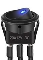
- One toggle switch
- Zip ties
- A battery, preferably 20V-40V with reasonable capacity. I use a 40V battery shared with my electric lawnmower.
Step 1: Build the Frame and Motor Mount


- In general you can attach the motor anyway you desire, this is just an example. The focus of this Instructible is on the electronic side.
- Cut the slotted angle metal to length.
- 3D print the parts from my Thingiverse for the framing supports and mounting the hoverboard motor https://www.thingiverse.com/thing:4980209
- Drill two holes on a ripstik to fit 5/16 bolts as shown in the picture.
- Put the bolts and nuts as shown in the pictures.
- The last picture is the finished product. I leave the back wheel for safety reason. When place on a flat surface, the motor is below the back wheel, therefore the back wheel is above the ground. Stepping on the ripstik put a pressure on the motor for traction.
Step 2: Electrical Connections to the Motor


Unlike a standard DC motor, brushless motors are controlled differently. DC (brushed) motors typically have (+) and (-) terminal which you apply a voltage. Brushless motors on the other hand, are driven by pulses at different phases, three phases in this case.
The 1st picture shows the wiring diagram of the motor driver. Additional wiring information:
- Short the "Direction Control DIR" to GND so the motor only rotate one direction (forward).
- Brake/Stop can be connected to a push button switch and connect it to 5V.
- Instead of using the motor driver 5V to connect to Wemos 5V, use the Buck Converter because it is more stable:
- Use the Buck Converter (+) output.
- Dial the Buck Converter until the output voltage is slightly higher than 5V for more margin should the voltage dip occasionally. I dialed it to 5.2V.
- Connect GND to Wemos GND
- Connect GND to Buck Converter output GND (or negative (-) output).
- Connect "Control Input" to Wemos D3 pin
- The battery can be higher than the hoverboard's battery. The driver is rated up to 60V and I use a 40V power tool battery.
- You can add a toggle switch for the battery, make sure it is rated for high current, instead of plugging the battery to power on.
Next: upload the following Arduino code to the Wemos:
#include <ESP8266WiFi.h>
#include <Arduino_JSON.h>
#define PWM_PIN 0 // D3
#define BREAK_PIN 5 // D1
JSONVar myJSON;
WiFiServer server(5001);
WiFiClient wificlient;
String request;
int Magnitude;
unsigned long last_no_signal = millis();
boolean Break, last_Break;
void setup() {
pinMode(PWM_PIN, OUTPUT);
pinMode(BREAK_PIN, OUTPUT);
digitalWrite(BREAK_PIN, LOW);
Serial.begin(57600);
analogWrite(PWM_PIN, 0);
WiFi.softAP("Ripstick", "anypasswordyouchoose");
Serial.print("AP IP: "); Serial.println(WiFi.softAPIP());
server.begin();
analogWriteRange(1023);
}
// ========================= Loop ==========================
void loop() {
request = "";
Magnitude = 0;
//Break = false;
wificlient = server.available();
if(wificlient) {
request = wificlient.readStringUntil('\n');
//request.trim();
myJSON = JSON.parse(request);
//wificlient.write("OK");
//wificlient.flush();
Serial.println(request);
// Set PWM power
Magnitude = 0;
if (myJSON.hasOwnProperty("mag")) {
Magnitude = int(myJSON["mag"]);
//Serial.println(Magnitude);
analogWrite(PWM_PIN, Magnitude);
}
// To break
if (myJSON.hasOwnProperty("but")) {
Break = int(myJSON["but"]) != 1;
if ( last_Break != Break) {
if (Break) {
digitalWrite(BREAK_PIN, HIGH);
} else {
digitalWrite(BREAK_PIN, LOW);
}
}
last_Break = Break;
}
wificlient.write("OK");
wificlient.flush();
last_no_signal = millis();
} else {
if ( (millis()-last_no_signal) > 500) {
analogWrite(PWM_PIN, 0); // no power when no signal
}
}
}
Step 3: Remote Control


- The remote control parts can be 3D printed from my Thingiverse: https://www.thingiverse.com/thing:4980209
- See the schematic picture of how to wire the remote control.
- Dial the Mini Buck Converter until the output voltage is around 5V (or slightly higher).
- The LED is used as an indicator when the Wi-Fi connection to the motor Wi-Fi is established which is when the LED is blinking.
- The potentiometer is used to control the speed or power of the motor
- The momentary push button switch is used for the brake.
- The toggle switch is used to power the remote control on and off.
Upload the following Arduino code to the Wemos:
#include <ESP8266WiFi.h>
#include <Arduino_JSON.h>
JSONVar myJSON;
WiFiServer server(5001);
WiFiClient wificlient;
String request;
char ch_O, ch_K;
bool is_LED_on;
unsigned long lasttime_led = millis();
#define BREAK_PIN 14 // D5
#define LED_PIN 13 // D7
void setup() {
pinMode(LED_PIN, OUTPUT);
Serial.begin(57600);
WiFi.enableAP(false);
WiFi.mode(WIFI_STA);
WiFi.begin("Ripstick","anypasswordyouchoose");
while (WiFi.status() != WL_CONNECTED) {
delay(500);
Serial.print(".");
}
Serial.println("");
Serial.println("WiFi connected");
Serial.println("IP address: ");
Serial.println(WiFi.localIP());
WiFi.setAutoReconnect(true);
WiFi.persistent(true);
pinMode(BREAK_PIN, INPUT_PULLUP); // D5
digitalWrite(LED_PIN, LOW);
}
void loop() {
//static bool is_LED_on = true;
//static unsigned long lasttime_led = millis();
//static int nn = 0;
int analogread;
if (!wificlient.connect("192.168.4.1", 5001)) {
Serial.println("Connection to Ripstick server FAILED");
delay(1000);
return;
}
analogread = analogRead(A0) * 4;
if (analogread > 1000) {
analogread = 1000;
}
myJSON["mag"] = analogread;
myJSON["but"] = digitalRead(BREAK_PIN); // D5
Serial.println(myJSON);
request = "";
wificlient.println(myJSON);
wificlient.flush();
request += char(wificlient.read());
request += char(wificlient.read());
//Serial.println(request);
// if (request.equals( "OK")) {
// Serial.println("Success " + String(nn));
//} // else no power to the motor
// nn = nn + 1;
if ( (millis()-lasttime_led) > 1000) {
if (is_LED_on) {
is_LED_on = false;
digitalWrite(LED_PIN, HIGH);
} else {
is_LED_on = true;
digitalWrite(LED_PIN, LOW);
}
lasttime_led = millis();
}
}
Step 4: Enjoy
Enjoy and use it cautiously, safety is everyone's responsibility. I was able to go 15 MPH (24 km/h) on a flat and smooth surface with no one around. Though I could faster, that was the maximum speed I would attempt. Be very cautious of your surrounding.


