

Introduction: Nikon IR Remote and Time Laps With ATtiny 85


Why take time lapse pictures.
The Nikon Coolpix P900 has very good build in features to take moon photos with it's 83 digital zoom.
To take moon photos the Nikon has a 2-second delay. Other time lapses build in features are very good.
Better even is a remote and a motorised tripod as the moon is constantly moving along. Time lapse photos can be merged to make a small movie with good software.
I had problems getting a remote to suit. The original ML-L3 Nikon remote at $ 39 Au was too expensive if you know that the copy from china sells for $1. So I wanted a quick delivery and bought in Australia for AU$ 4.15 that did not work at all.
Then I purchased a universal remote [pro]master that did not always work.
That made me even more determined to build my own.
But better, I can now program the chip to take a photo in intervals every second.
In the software it is in line 26 delay(5000); // That is 5 seconds.
Do not write delay(60*1000); as you see it in Adafruits software. It does not work for the Tiny and only takes one photo at the start up.
With the software you can set the seconds or minutes you prefer for you own circumstances and it is not limited to the Nikon camera.
You can use any camera that has an infrared sensor.
I searched everywhere to get the software and found the best tutorial was from Lady Ada at Adafruit.
That saved me a lot of explaining here.
https://learn.adafruit.com/ir-sensor/overview
I liked this tutorial as I did not have to make many changes to the software.
I first tried this with the Arduino Nano that worked fine but wanted it smaller.
My all time favorite is the ATtiny 85.
How to program them, you find in my Instructables.
https://www.instructables.com/id/Programming-ATtinys-Micro-Controllers-With-Arduino/
UPDATE 16 February 2016
I have updated pictures with different battery voltage supplies.
Every time the voltage changes the resistors have to change as well.
At 3.6 Volt I left out the LED as it only uses power unnecessarily and drains the battery too quick.
Then I recommend to use a LIPO battery They charge at 4.2 Volt and have 3.7 volts.
Using 3x AA 1.5 volt batteries is another option. A new battery actually has 1.6V.That is why in the picture you see 4.8 Volt.
The LEDI calculated with a test method I described in my EMF meter Instructable.
My red LED has a forward voltage of 1.84 V and 3.37 mA.
My Clear LED has a forward voltage of 2.76 V and 2.38 mA.
Formula: R = (Vs - Vf) / If
Another good LED calculator http://www.digikey.com.au/en/resources/conversion-calculators/conversion-calculator-led-series-resistor
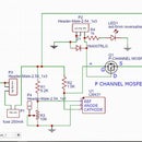
Step 1: Construction of the Time Laps Infrared Remote


Best is to have both a momentary push button and an on/off switch.
When switched on it takes a photo, but then keeps going with the set time interval till you turn the remote or the camera off.
With a 32 GB card at 4608 x 3456 pixels and with the Fine quality, you can take about 3900 photos on the Nikon P900. At the smaller image sizes, such as 3264 x 2448 pixels, with Fine quality, the same card can hold 7800 images. At the smaller image sizes, such as 1600 x 1200 pixels with the Fine quality the card can hold more than 10,000 images.The image number varies with the aspect ratio and subject matter.
If you are seriously interested in the camera, I recommend this book from Amazon.com.au
I do not get paid to say this, but I have started reading it and like it as the manual does not explain how to get the most from Nikon's Superzoom Digital Camera.
http://www.amazon.com.au/gp/product/B0101IEOG6?key...
Construction
You will need
1x ATtiny socket
1x ATtiny85 20PU http://www.ebay.com.au/itm/191736193534?_trksid=p2...
Arduino UNO and programmer shield to program the tiny
1x 940nm 5mm IR Infrared transmitter http://www.ebay.com.au/itm/10x-940nm-5mm-IR-Infrar...
1x 1K resistor,//
I now experimented more and found that the IR I used from an old remote worked fine
with 1 K.
For 5 volt or better 3x AA 4.5 volt supply, a 1 K resistor is good and 680-ohm resistor is fine for a 3.6 volt supply.
The IR has about a forward voltage of 1.2 to 1.14 volt and 4.06 to 4.12 mA power consumption.
With your voltage supply and those two figures above you can calculate your resistor at
http://led.linear1.org/1led.wiz
1x 220 ohm to 560 resistors for the LED (see photos)
1x LED 5mm any color
1x battery 5 volts or as I have used the 3.6 volt button cell. Only available at Battery world $5 or china.
NOTE, at 3.3 volts the unit does not work. And two button cells are too high for the ATtiny (max 5.5V)
http://www.ebay.com.au/itm/10-pcs-lot-rechargeable...
1x battery holder http://www.ebay.com.au/itm/5pcs-Button-Battery-Hol...
Or just use 3 x 1.5 volt AAA batteries. (4.5 volt)
Best (if you have a 3D printer) to print your own battery holder for your AAA batteries.
I bought two Cocoon create 3D printers from ALDI. Just fantastic quality prints for the price.
http://www.thingiverse.com/thing:456900/#files
1x push-button switch http://www.ebay.com.au/itm/50PCS-6x6x6mm-Micro-Min...
or switch or both
1x perhaps a case to fit the remote in
As there are no 5 Volt batteries, and if you use two button cells at 6.6v a 7805 voltage regulator can be added. Minimum input usually 7 volts.
https://www.sparkfun.com/datasheets/Components/LM7805.pdf
To take photos of the moon you will need the Nikon P900 under Au$670.- from Harvey Norman when they have a sale going.
http://www.harveynorman.com.au/catalogsearch/resul...
1x tripod at good quality from $250
check out the user Manual
http://downloadcenter.nikonimglib.com/en/products/...
check out where the moon is, sunrise and sunset. It is a map-centric sun and moon calculator.
Step 2: Software for ATtiny 85


This program goes in your Arduino folder usually found in my Documents. If you can not find it, check
File, Preferences. There you can see your Sketchbook location.
Close your Arduino IDE. Or close it after, then re-open the IDE so that the IDE "the Arduino program" detects the software.
I used pin 2 for the IR with 1K resistor.
and added a green LED on pin 3 with a 200-ohm resistor also suitable for 5 volts.
The led turns on just before the time lapse takes a photo. To show the user something is happening.
You can comment the line out // to save battery power and leave the lLED away.
Note that the battery has 3.6 volts and not 3 volts.
The 3-volt batteries you get everywhere.According to the data sheet, they work.
I have not tried them out.


Step 3: More IR Tutorials


How to program the chip is not in detail as you find the info in Instructables.
https://www.instructables.com/id/Programming-ATtinys-Micro-Controllers-With-Arduino/
I assume this is plenty of info for you to construct your own.

![Tim's Mechanical Spider Leg [LU9685-20CU]](https://content.instructables.com/FFB/5R4I/LVKZ6G6R/FFB5R4ILVKZ6G6R.png?auto=webp&crop=1.2%3A1&frame=1&width=306)


