

Introduction: IoT Personal NodeMCU ESP12 WiFi Wireless Weather Station


In this Instructable I'm going to show you how to build personal wireless weather station using NodeMCU (ESP12)
One year ago I was create weather station based on Arduino. But always there are ways how to improve things to be better. New version need less power consumption. Rain reset 24h more precise, because time update from NTP server. Add OTA (Over the Air) compability to update is the process of loading a new firmware to
ESP8266 module using WiFi connection rather than a serial communication.
NodeMCU (ESP12) WiFi module will send sensors data to www.wunderground.com , https://weathercloud.net , https://thingspeak.com, https://www.pwsweather.com, www.windy.com
A Weather station is a device that collects data related to the
weather and environment using many different sensors. We can measure many things like:
- Temperature
- Humidity
- Wind
- Barometric Pressure
- UV index
- Rain
Step 1: Types of Sensors Used for Weather Station


The following is a list of measurement devices that are used in weather stations:
1) NodeMCU (ESP12) main board
2) Thermometer SHT31 thermometer measures temperature. You can measure both the temperature indoors and outdoors, record highs and lows, show trend arrows to indicate temperature rising or falling, and even predict short-term future temperature ranges.
Hygrometer SHT31- A hygrometer measures relative humidity. Relative humidity is the quantity or percentage of water vapor (water in gas form) in the air. Humidity influences environmental factors and calculations like precipitation, fog, dew point and heat index.
3) Barometer (BME280) – A barometer measures atmospheric pressure. A barometer can help to forecast upcoming weather based on the changes it measures in the atmospheric pressure.
4) Davis 6410 anemometer measures how fast the wind is blowing, or wind speed.
ESP8266 weather stations can display wind speed in MPH, KPH or knots, and record current, peak and average wind speed readings.
Wind Vane – A wind vane, or weather vane, is an instrument that determines which direction the wind is blowing.
5) Rain gauge measures rainfall or liquid precipitation
Step 2: Schematic and Wiring Diagram

Step 3: NodeMCU PCB Weather Station Shield


Design printed circuit board (PCB), I was used ,,Sprint-Layout" software. Exported to Gerber files. PCB was made https://jlcpcb.com
To create this NodeMCU ESP12 weather station shield you will need:
- NodeMcu Lua CH340G/CH340/ ESP8266 Wireless WIFI Internet Devolop Module Ebay
- Waterproof Digital Thermal Probe or Sensor DS18B20 Arduino Sensor Ebay
- JST-XH Kit 4Pin 2.54mm Terminal Housing PCB Header Wire Connectors Ebay
- Atmospheric Pressure Sensor Temperature Humidity Sensor Breakout BME280Ebay
- 2x 1K 0805 resistor
- 1x 120R 0805 resistor
- 2x 4.7K 0805 resistor
- 1x 10K 0805 resistor
- 1x RJ45 socket Ebay
- 1x 47uF electrolytic capacitor
- 1 x 40pin 2.54mm Female Single Row Breakaway Pin header Ebay

Step 4: Arduino Code


!!!! New version ESP8266 library will not work. At this moment only works old version. For example 2.4.2
Board manager ESP8266 - 2.4.2
1. Instal ESP8266 board into Arduino http://esp8266.github.io/Arduino/versions/2.0.0/do...
2.Enter your's Wifi router ssid and password.
- const char* ssid1 = "xxxxxxxxxx";
- const char* password1 = "xxxxxxxxxx";
3. Before upload code into your NodeMCU you will need register in wunderground.com to obtain a WU station ID and Key.
- char ID [] = "xxxxxx";
- char Key [] = "xxxxxx";
4. Register in weathercloud.net to obtain Weathercloud ID and Key.
- char ID2 [] = "xxxxxxxx";
- char Key2 [] = "xxxxxxxxxxx";
5. Register in pwsweather.com to obtain pws station ID and Api key
- char ID5 [] = "xxxxxxx";
- char Key5 [] = "xxxxxxxxxxxxxxxxxxxxxxxxxxxxxxx";
6. Change altitudepws in meters (m) to get relative pressure.
7. Register in thingspeak.com to obtain apiKey
- String apiKey ="XXXXXXXXXXXXXXX";
8 Register in Windy to get API key
char WINDYPAGE [] =
9. Change timezone to correct time zone
- const int timeZone = 2; //GMT +2 )
I'm using 30 second loop time sending data to Wunderground.com. And 10 minutes loop time sending data to Weathercloud.net and Thingspeak.com
Last edit: 2023 06 15
2020 02 01 - Fix Wunderground.com upload protocol
2020 06 01 - Replace DS18B20 sensor with DHT22, Add rain counter to save in eeprom
2020 09 25 - Correct time sync from NTP server. Add time zone
2021 04 07 - Correct rain tip count write to eeprom
2021 06 24 - Fix Weathercloud.net upload protocol
2021 06 27 - Add upload protocol to Pwsweather.com
2021 07 02 Add upload protocol to Windy.com
2023 06 15 - Fix Windy.net upload protocol.
Replace DHT22 sensor with SHT31
Libraries download link >>> https://drive.google.com/u/0/uc?id=13S3nuOyM5pTfKrUkRHQFMLDRY1NRimir&export=download
Step 5: Testing Weather Station


NodeMCU ESP12 is sending sendors data to wunderground.com, weathercloud.net, pwsweather.com, windy.com, and thingspeak.com.
So it looks everything it's working. Job done.
Mine weather station which you can check >
Step 6: OTA Over-the-air Programming


OTA (Over the Air) update is the process of loading a new firmware to
ESP8266 module using WiFi connection rather than a serial communication. This type of functionality is extremely useful in case of no physical access to the ESP module.
Uploading a new sketch wirelessly from Arduino IDE is intended for the following typical scenarios:
- during firmware development – as a quicker alternative to uploading a new sketch over a serial
- for updating the firmware of multiple ESPs in your network
Prepare for OTA capability
- Install Python on Your System
You need to install python27 on your system in order to program ESP8266 from your system you need to run OTA script. Install python27 on System from where your going to upload firmware. - Download and Install Arduino OTA Library Download The library and tools required for OTA
- Install "ArduinoOTa.zip" in arduino library.
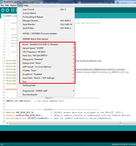
- Go to Tools to select your ESP board model. You also have to choose your ESP’s COM port
Upload file ,,IoT_Personal_NodeMCU_ESP12_WiFi_Wireless_Weather_Station.ino"
- Press the “Upload” button in the Arduino IDE and wait for the “Done uploading” message
Uploading a new sketch OTA (Over the Air)
Now your ESP8266 is ready to receive OTA firmware updates. You can
unplug your ESP8266 from your computer and power it through any power source. If your ESP8266 has a wireless connection to your router, you should be fine to upload new firmware.
- Go to your Arduino IDE. Open Tools tab select the Port option and you should see something like this:
Nodemcu_weather_station and your_esp_ip_address
- Open your modified Nodemcu_weather_station.ino and upload over the air.
Info is taken from (Rui Santos)
https://randomnerdtutorials.com/esp8266-ota-updates-with-arduino-ide-over-the-air/
Step 7: Solar Radiation Shield


Solar Radiation Shield is made from flower pot lower pad


Step 8: Installing Personal Weather Station


The location weather station is the most important part of installation. If weather station is located under a tree or an overhang, the rainfall data measured by the station will not be correct. If you place your weather station in an alley, you could very well get a wind tunnel effect on the anemometer, resulting in erroneous wind data. Weather station should have good "fetch", or distance from any other tall object. The standard wind measurement should be taken at 10 meters above the ground. A roof-top works the best for me. Weather station is powered from solar panel. So it is autonomous.
The most common error in installing a weather station is associated with misplacing the thermometer sensor. Meteorologists define temperature as the temperature in shade with plenty of ventilation. When placing weather station, make sure:
- The thermometer sensor never receives direct sunlight.
- The thermometer receives plenty of ventilation and is not blocked from the wind.
- If the thermometer is placed on a roof-top, make sure it is at least 1.5 meters above the roof-top.
- If the thermometer is placed above grass, again, it should be at least 1.5 meters above the grass surface.
- The thermometer is at least 15 meters from the nearest paved surface.
So I'm using weather shelter. Solar Radiation Shield is made from flower pot lower pad. This way, weather station can be placed in direct sunlight, with the thermometer located inside the shelter. More information about installing weather station here
Step 9: WiFi Signal Quality


Added compatibility to check WiFi signal quality. If your weather station is to far from your router, you will lost communication. So you can try to mount weather station where WiFi signal strength is higher.
Step 10: 3D Tipping Bucket Rain Gauge and Calibration


Tipping bucket rain gauge 3D link >> https://www.thingiverse.com/thing:4519605
Mine 3d funnel diameter - 95mm 9.5cm ( radius 4.75cm)
Funnel area S= pi *r2 = (3.14 * (4.75 *4.75)) = 70.88cm2
Mine syringe for calibration is 24mm. 24 ml give me 9 tips.
24mm / 70.88cm2 = 0.338cm 3.38mm 3.38mm / 9 tips = 0.375mm
So one tip is 0.375 mm ( 0.0147 inches)


Step 11: Info Is Taken From:
- Cactus.io http://cactus.io/projects/weather/arduino-weather...
- Jakub Nagy https://www.instructables.com/id/Arduino-Weatherc...
- Jordan Blanchard http://chynehome.com/web/station-meteo-a-base-de-e...
- Wunderground.com PWS Upload Protocol https://docs.google.com/document/d/1KGb8bTVYRsNglj...
- Davis 6410 vane manual https://www.davisinstruments.com/product_documents...
- Abhijit Borah https://www.instructables.com/id/Arduino-Rain-Gaug...
- Windy PWS upload protocol https://community.windy.com/topic/8168/report-your-weather-station-data-to-windy


