

Introduction: One and Multiple Servo Motor Control With ESP32 Development Board


This article covers controlling a Servo motor using the ESP32 development board. Also, this article provides some basic information about the Doit ESP32 Devkit V1 development board, MG996R or MG995 Servo motor, and breadboard circuitry, as well as a step-by-step guide for assembling a printed circuit board designed for multi-servo motor control. In addition, the shown breadboard circuit and printed circuit board minimize the jitter problem of Servo motors, making Servo motors work more stably.
Step 1: About ESP32 Board and Servo Motors

Doit ESP32 Devkit V1 Development Board
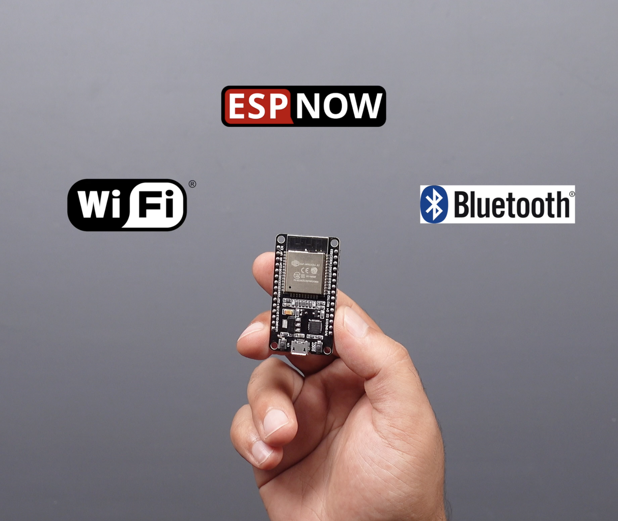
The Doit ESP32 Dev Kit V1 is an ideal board for development purposes, powered by the ESP32 microcontroller. It comes with Wi-Fi and Bluetooth connectivity features and offers a wide range of pins for various applications. You can refer to the pinout diagram of the board to determine the pin you'll use for servo motor control in our project. DOIT ESP32 Board can operate with a supply voltage between 4V to 12V via a VIN pin.
MG996R or MG995 Servo Motor
The MG996R or MG995 servo motors are a popular choice known for their high torque and quick response time. Servo motors are precision motors that can be moved to a specific angle or position. They are generally used in robotics and automation projects. The servo motor can operate with a supply voltage in the range of 4.8V to 6V. However, servo motor control can sometimes be accompanied by a common issue called Servo Jitter. Servo jitter refers to the undesired trembling or small fluctuations exhibited by a servo motor. It indicates an unstable operation and can lead to undesired results.
Step 2: Build a Circuit on the Breadboard


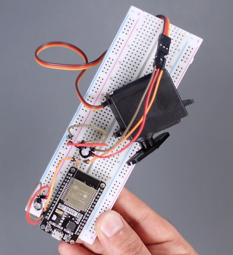
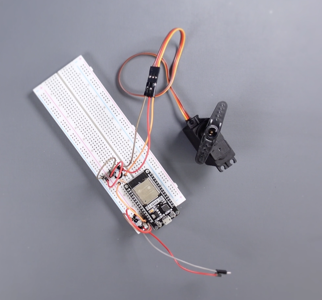
Build a circuit on the breadboard. Your circuit should have the following components:
- Doit ESP32 Devkit V1 development board
- MG996R or MG995 servo motor
- 100uF capacitor (for power supply)
- 470uF capacitor (for servo motor power supply)
- 330-ohm resistor (for the signal leg of the servo motor)
To avoid the servo jitter issue, I have included specific components in the breadboard circuit. So what do these components do to avoid the servo jitter issue? These components help reduce power fluctuations on the circuit and ensure the servo motor operates more stably. The capacitors absorb power supply fluctuations, stabilizing the servo motor's power feed, while the resistor helps minimize electrical noise on the signal line, allowing cleaner transmission of the servo motor's signal. By incorporating these components, the breadboard circuit minimizes the servo jitter issue, enabling the servo motor to operate more reliably.
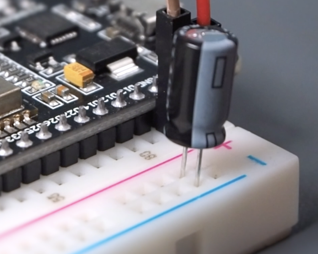
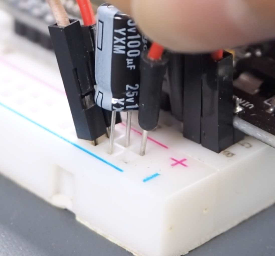
- Place the ESP32 on the breadboard. Add wires to VIN and GND inputs for power. Then add the 100uF capacitor and attach the power wires to the capacitor's legs. Make sure the polarity is correct!
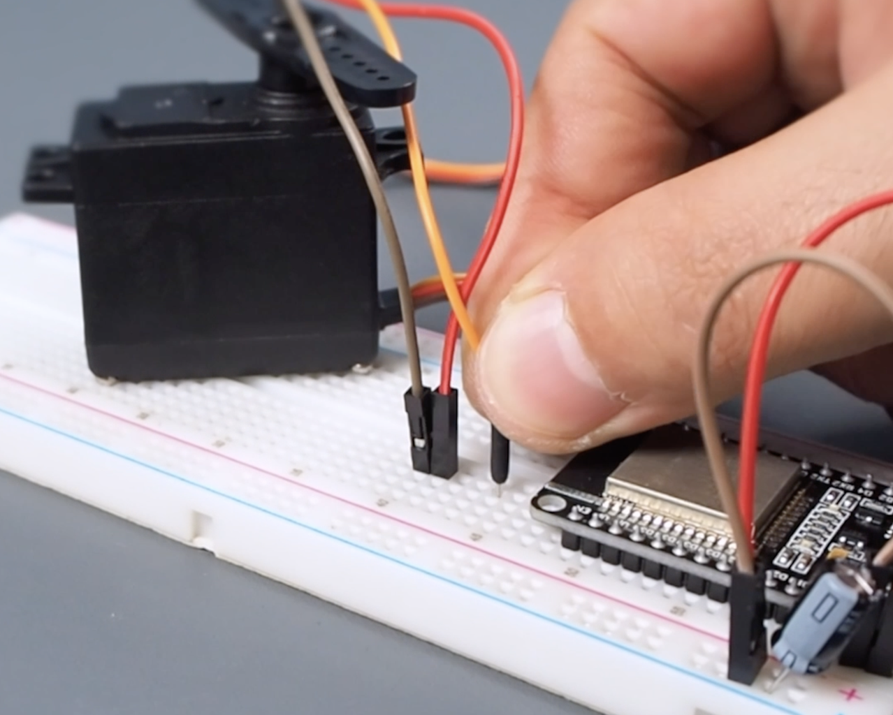
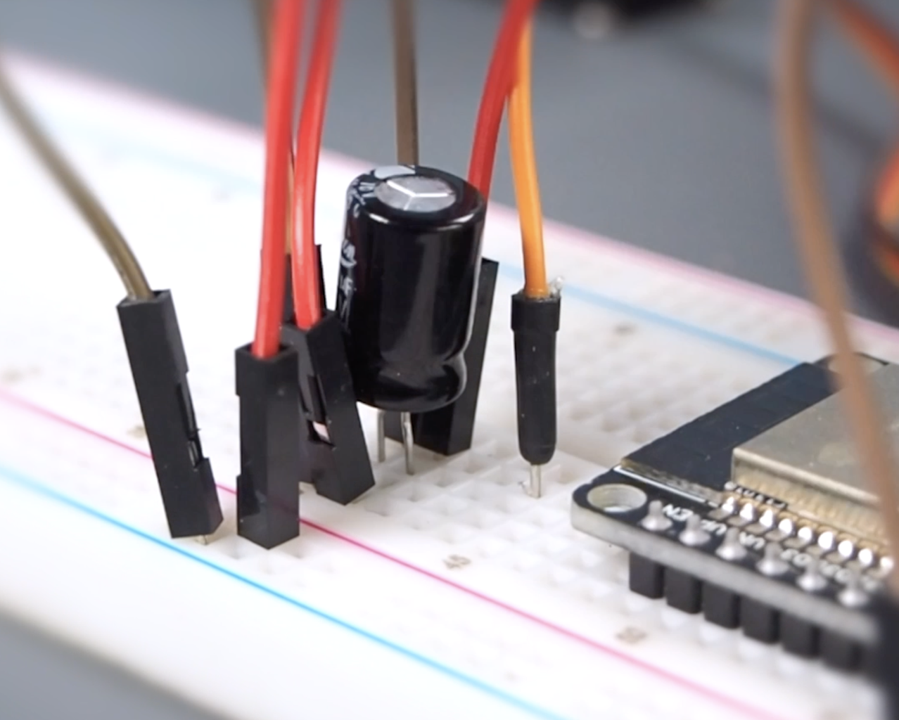
- Place the ground, power, and signal wires of the servo motor, add 470uF capacitor to the ground and power inputs of the servo, then connect the capacitor's legs to the breadboard power and ground lines.
- Add a 330-ohm resistor to the signal leg of the servo, connect the wire signal pin of the servo motor to pin GPIO13 of the ESP32, and connect this wire to the other leg of the resistor.
Step 3: ESP32 Development Board Setup for the Arduino IDE


To work with the Arduino IDE, we need to set up the ESP32 board. Here are the requirements and steps:
- Download and install the latest version of the Arduino IDE from the official Arduino website.
- Open the Arduino IDE and go to "Preferences" > "Board Manager URLs", paste the shared ESP32 package link, and click the ok button.
- Navigate to "Tools" > "Boards Manager."
- Search for "ESP32" in the Boards Manager and install the ESP32 boards.
- Select the appropriate ESP32 board from the "Tools" > "Board" menu.
Additional Boards Manager URL:
https://raw.githubusercontent.com/espressif/arduino-esp32/gh-pages/package_esp32_index.json
Step 4: ESP32 Servo Library and Circuit Test
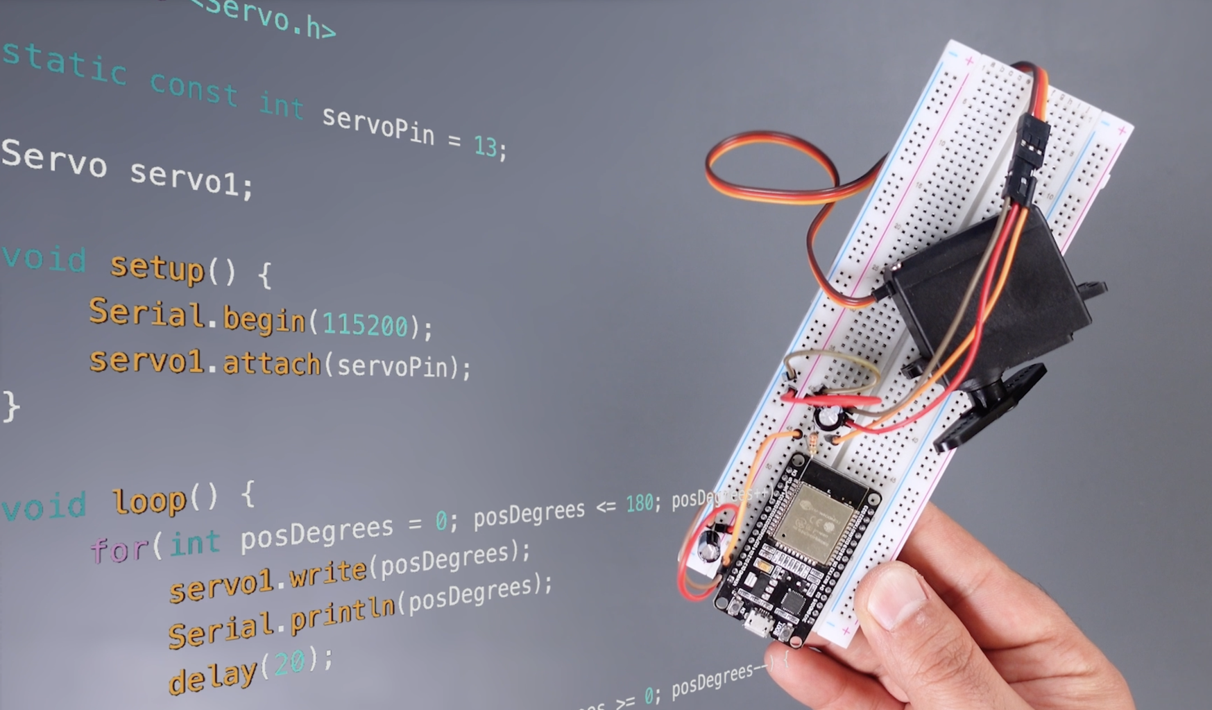


To test the circuit, we can utilize the "Simple Servo" example provided by the ESP32 Servo library. Follow these steps:
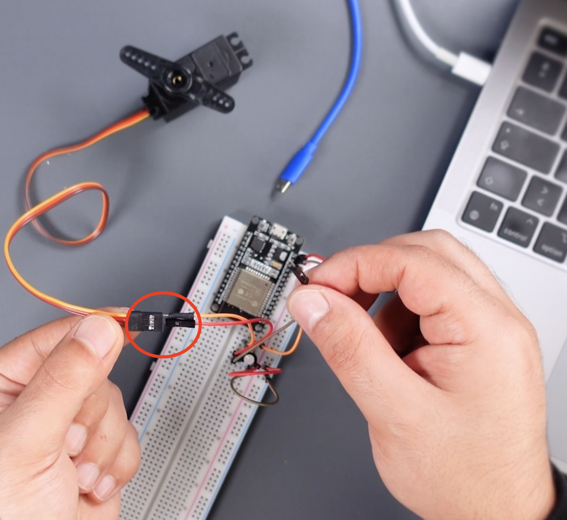
- First, cut off the servo power without making the USB connection. Then open the Arduino IDE.
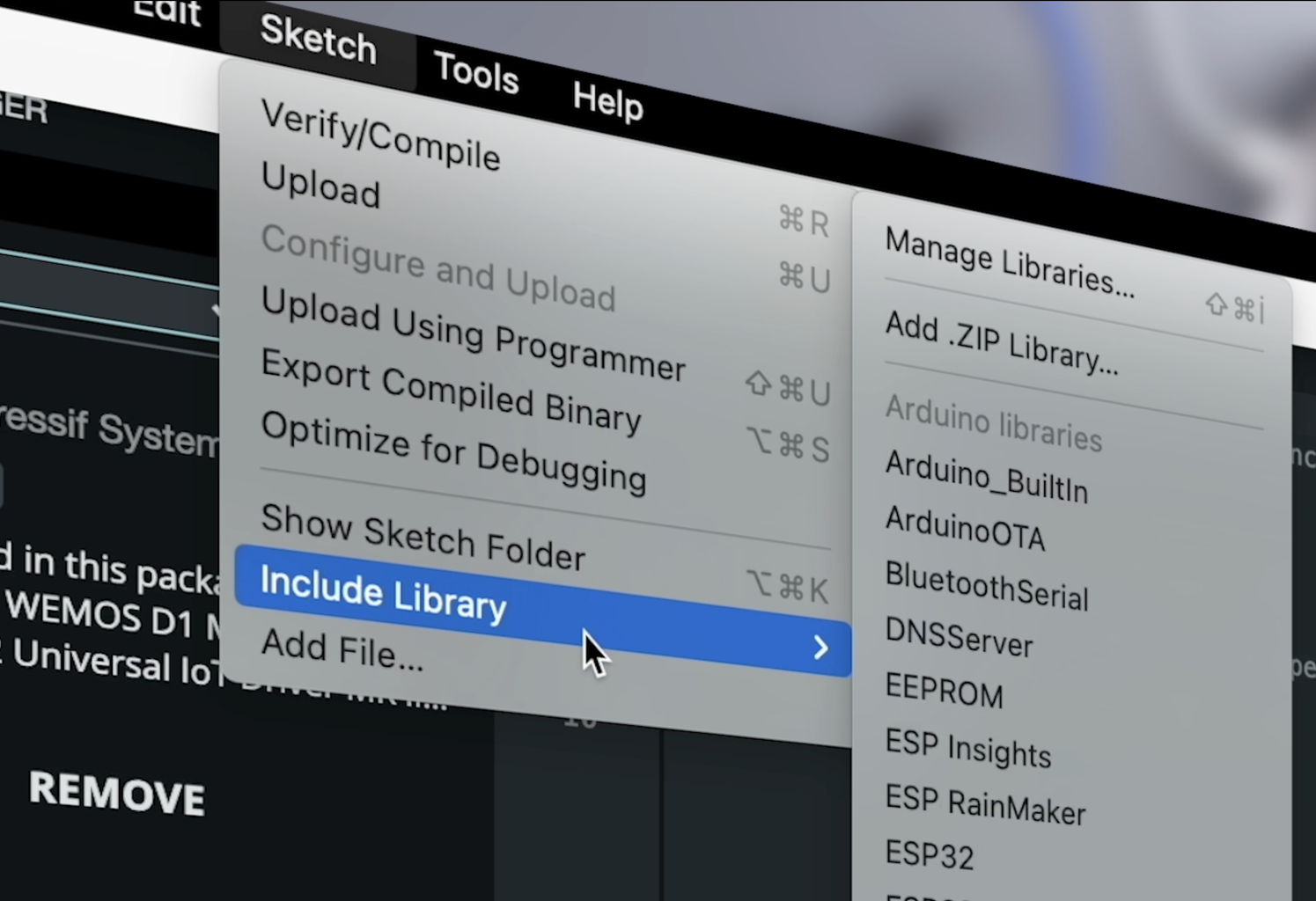
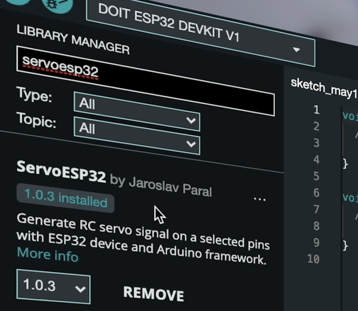
- Go to "Add Library" from Sketch, search Servo library for ESP32, and install it.
- Go to "Examples" from "File", find the "Simple Servo" sketch for ESP32, and open it.
- Define the PIN the Servo is connected to and upload the code!
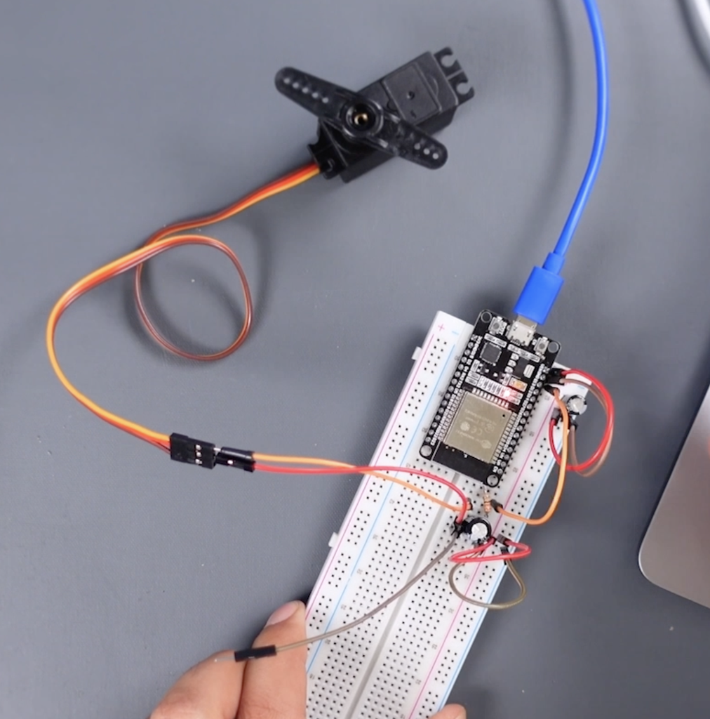
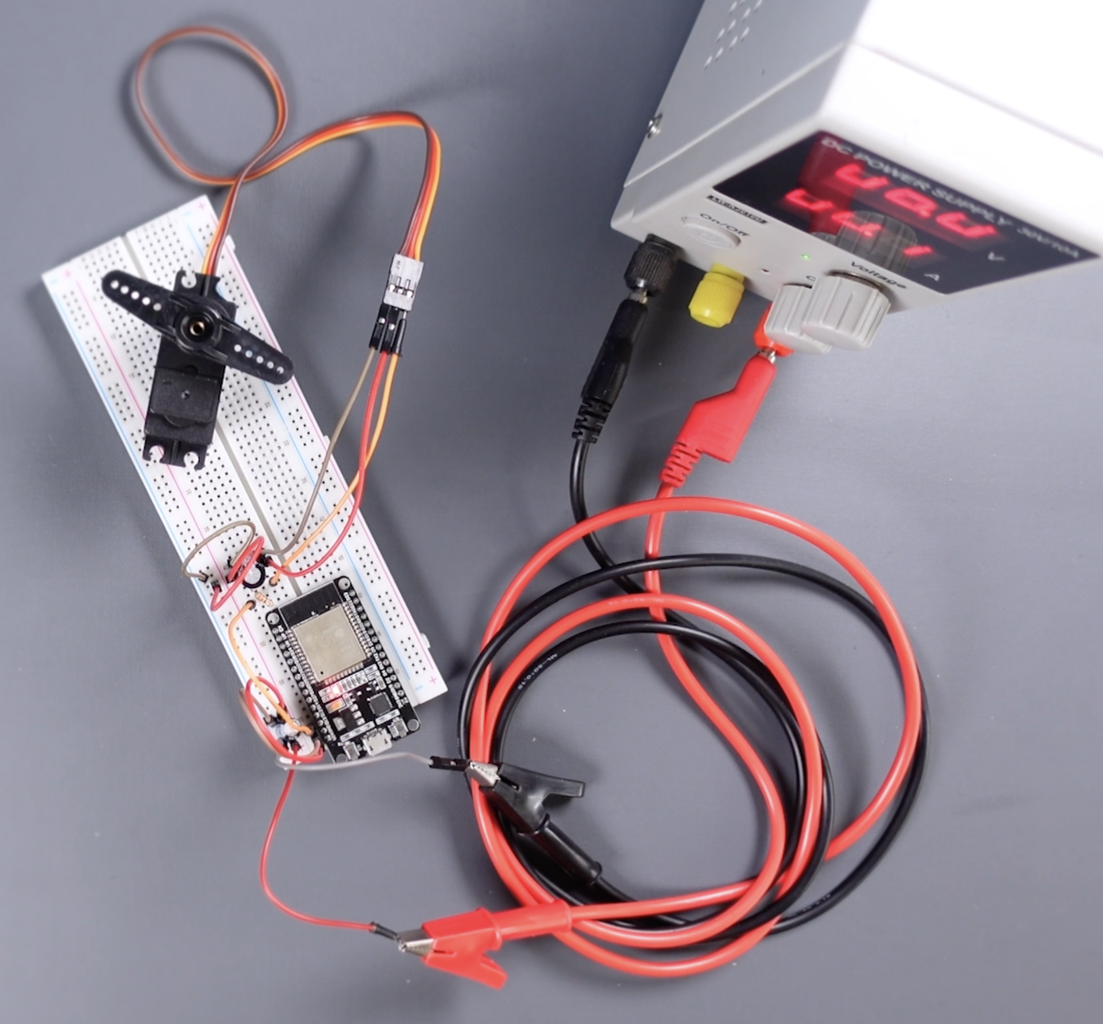
- Reconnect the wire of the servo power, then let's power the circuit.
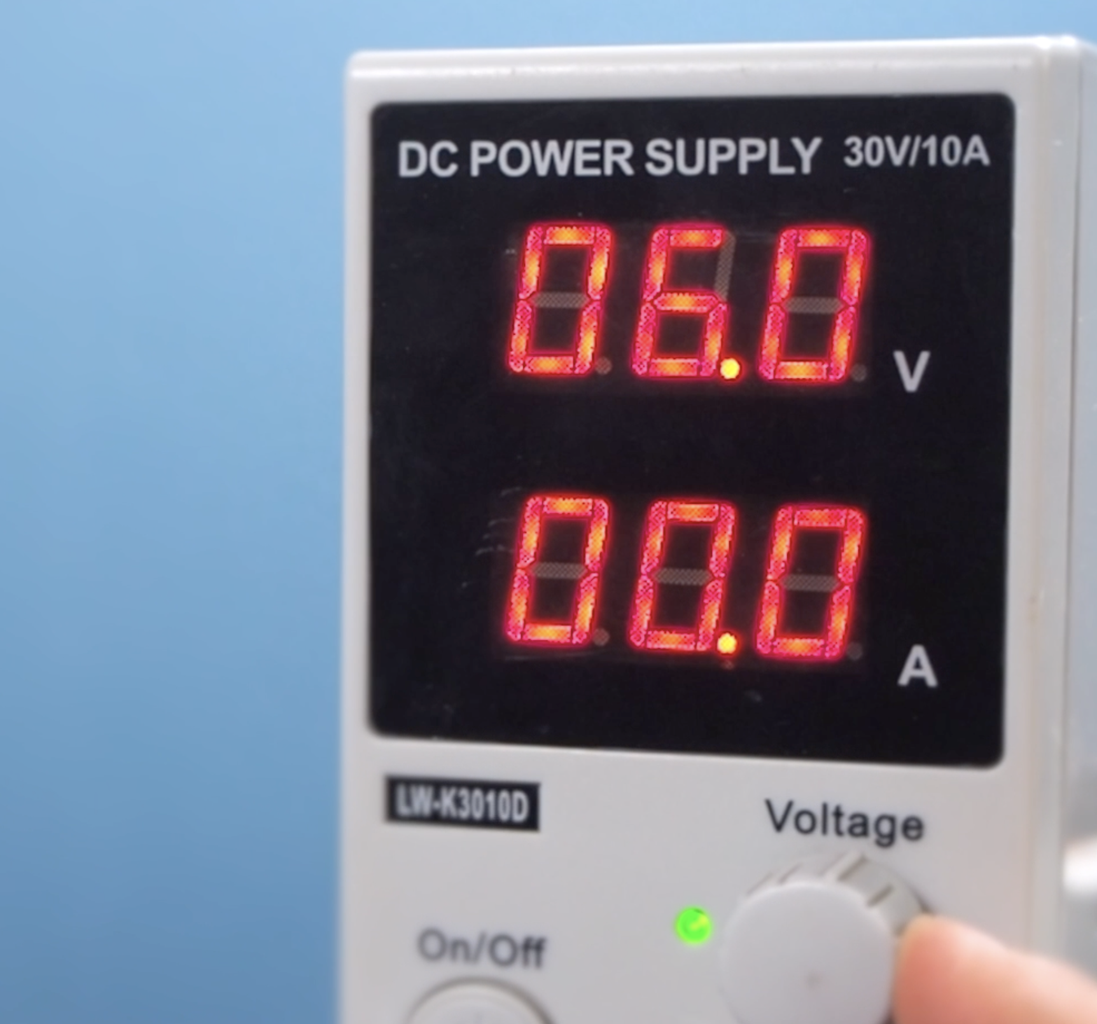
DOIT ESP32 Devkit V1 Board can operate with a supply voltage between 4V to 12V via a VIN pin. The servo motor can operate with a supply voltage in the range of 4.8V to 6V. Therefore, a 6-volt supply voltage will be sufficient for the circuit. Power the circuit with a 6-volt external power supply and observe the servo motor operating smoothly. Verify that the servo jitter issue is not present during the test. The circuit works great... Let's move on to multiple-servo control.
ServoESP32 Library:
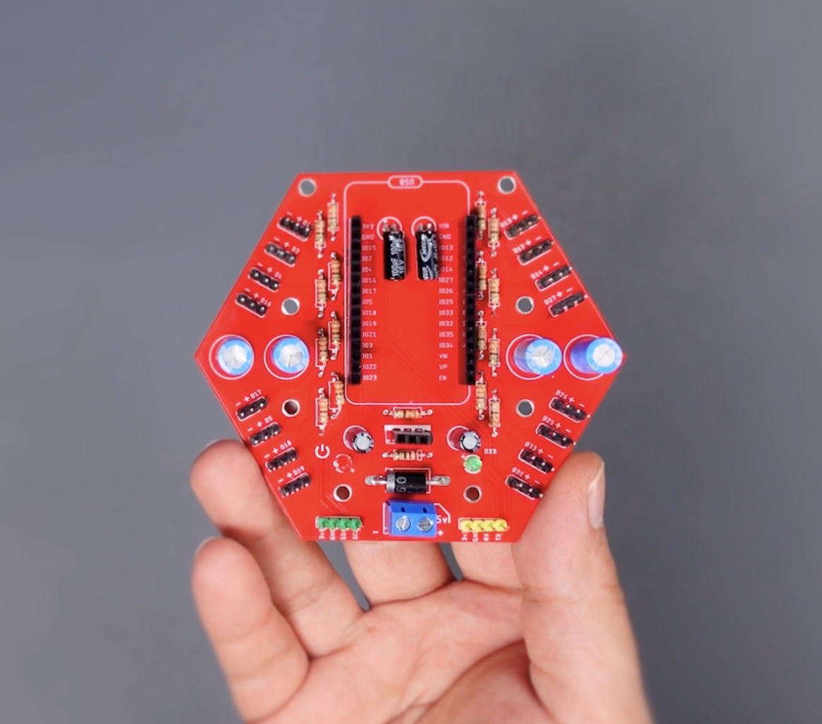
Step 5: Printed Circuit Board (PCB)


As the breadboard circuit can become complex when controlling multiple servo motors, I designed a printed circuit board (PCB) to provide a more organized and permanent solution. Because breadboard circuits are ideal for testing and running small-scale designs, they are not durable for long-term use. Printed circuit boards are used to design electronic circuits more durable and stable for long-term use.
Place an order with a PCB fabrication service provider to produce the designed PCB. I prefer the PCBWay for printed circuit board service, I can easily upload the design file and place an order quickly. The order is delivered within a few days, depending on your location. You can choose PCBWay for high-quality and low-price PCB service.
PCB Order:
- Go to PCBWay's official website.
- Then go to the "PCB Instant Quote" link.
- Click on the "Quick-Order PCB" link from the page that opens.
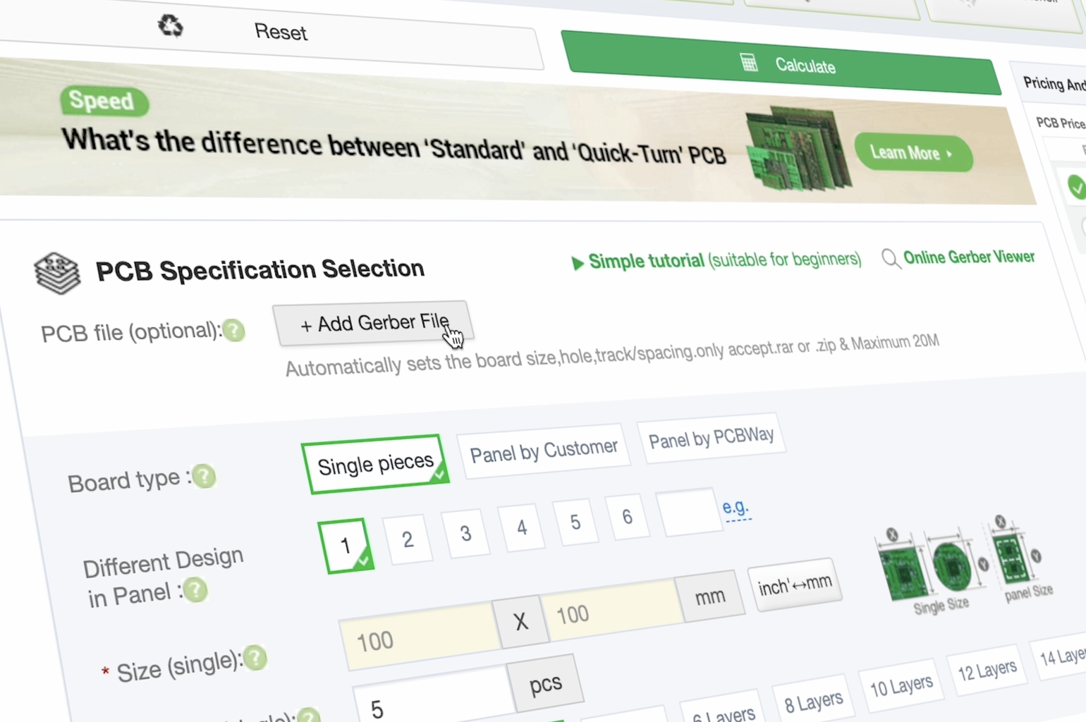
- Click "Add Gerber File" and then get the Gerber file shared in the link below and upload it.
- A minimum 5 PCB pieces option is selected as standard. You can increase the number of PCBs if you wish, or you can get 5 PCBs for $5.
- Finally, you can complete the order by choosing one of the "Solder Mask" color options.
Features of the PCB:
The designed PCB is a 2-layer board that can handle up to 16 servo motors. It includes an ESP32 microcontroller for seamless integration and control.
PCB Design (Gerber) File:
Step 6: PCB Assembly and Soldering


Just like the breadboard circuit, easy-to-assemble solderable components were preferred:
- 4x 100uf 25V~16V Capacitor for Power
- 4x 470uf 25V~16V Capacitor for Servo Motor
- 1x SB560 Diode for Power
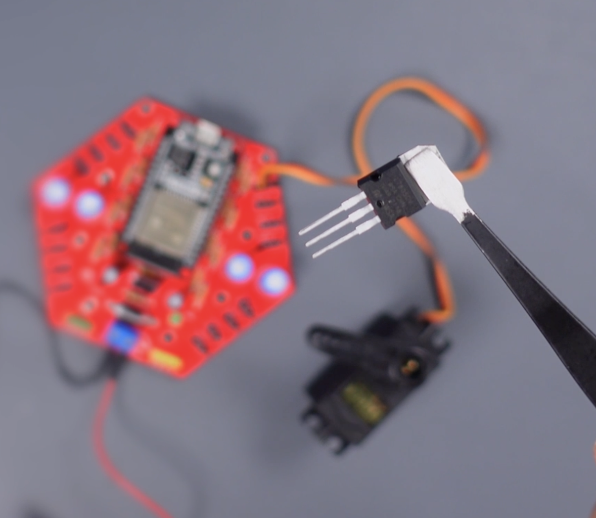
- 1x 7805CV Voltage Regulator for Power (Used when required, see explanation in next step)
- 2x 3mm-LED
- 16x 220-ohm Resistor for Servo Motors
- 2x 330-ohm Resistor for LEDs
- 1x 2pin 5mm Screw Terminal for Power input
- 2.54 Female Headers for ESP32 Board
- 2.54 Male Header for Servo Motor Connections
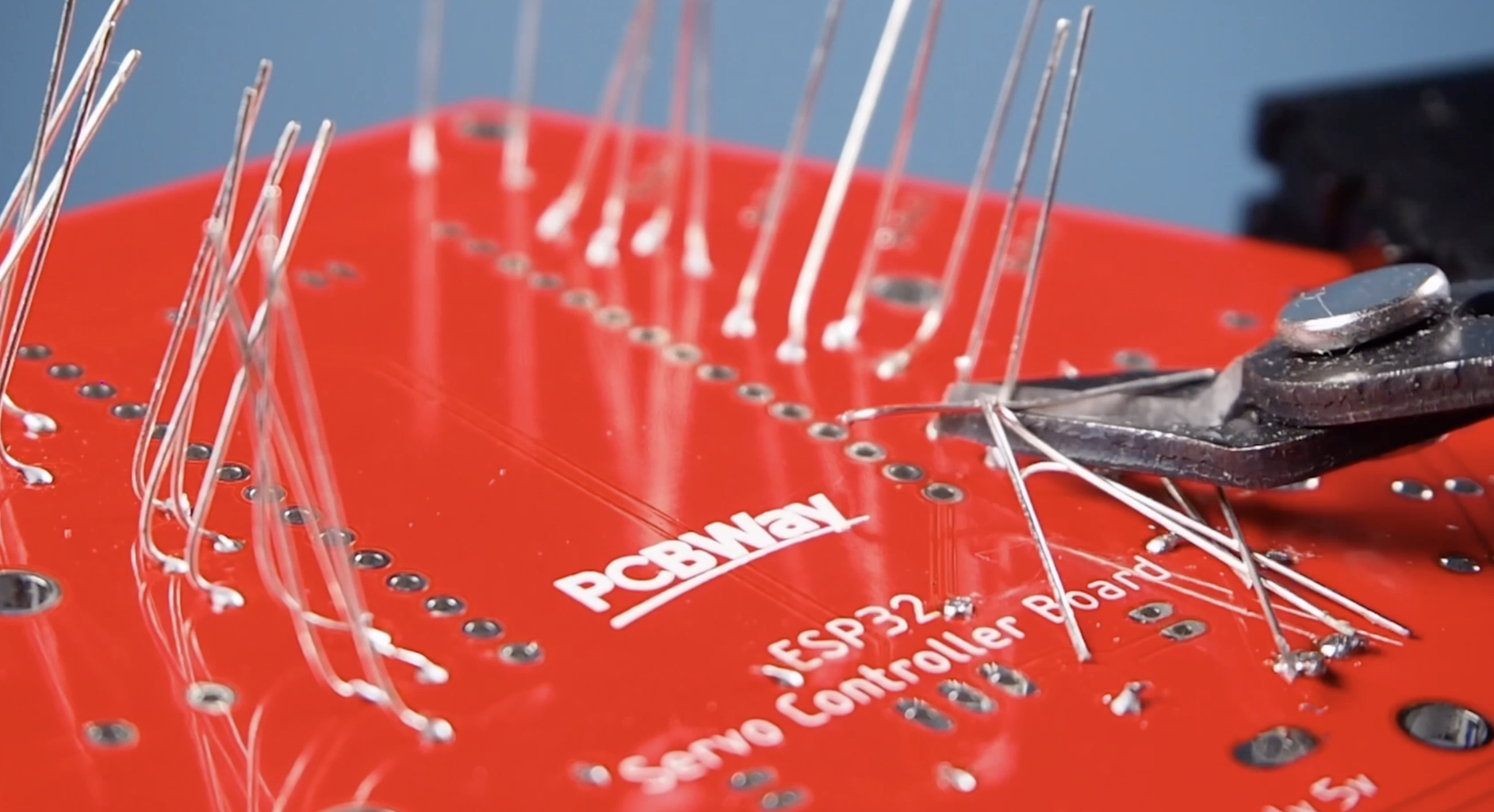
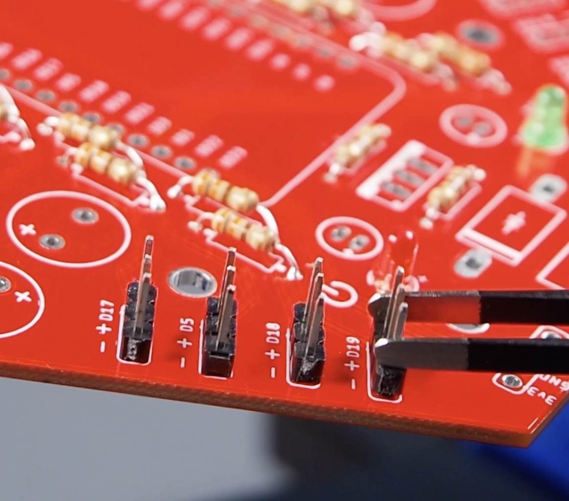
Assemble the required components on the PCB, and solder them in place with the soldering iron and soldering wire. You can see the soldering priority of the components in the uploaded images. It will make your work easier if you proceed according to the component dimensions while doing the soldering process.
- Put the resistors and LEDs in place, then solder them.
- Shorten the leg lengths of the components using a wire cutter.
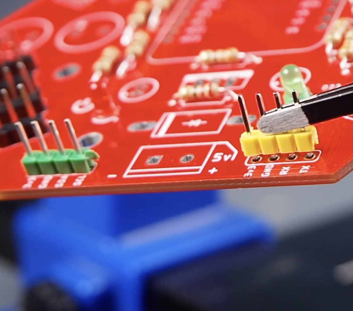
- Then add and solder the male-female headers. You can use paper tape to prevent the headers from coming off during soldering.
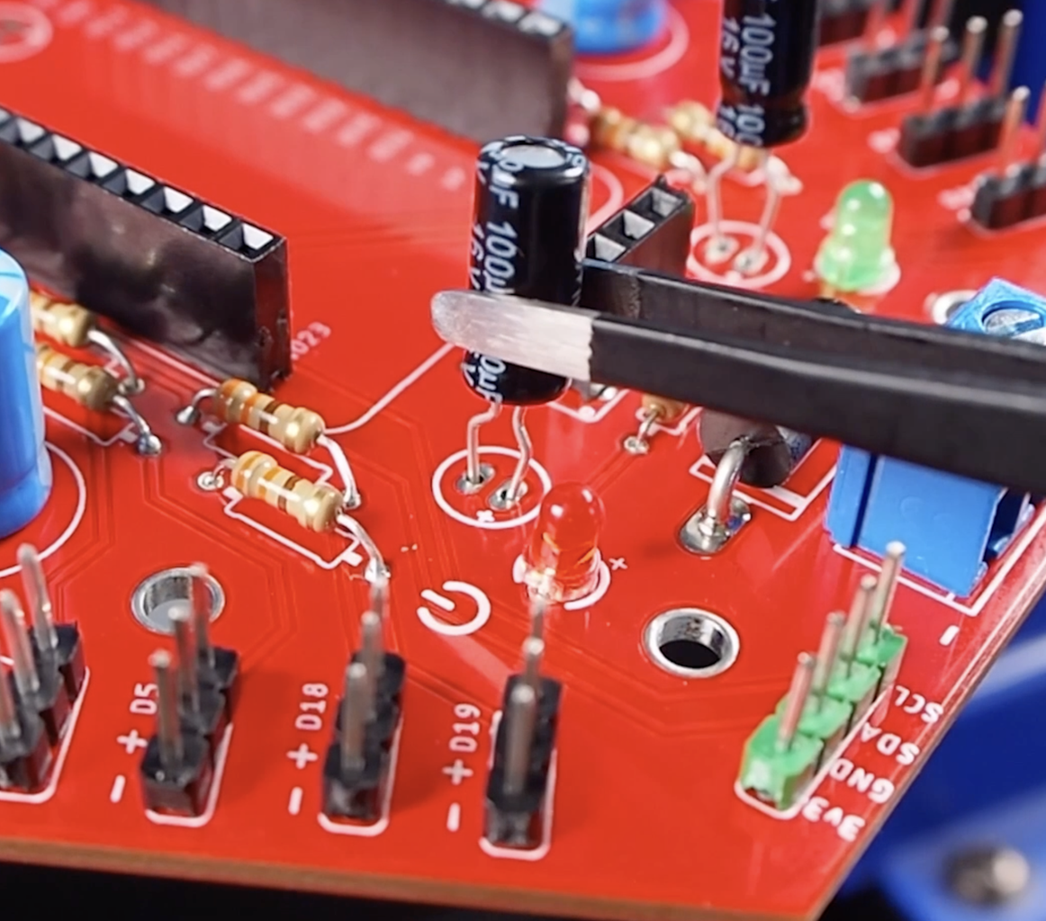
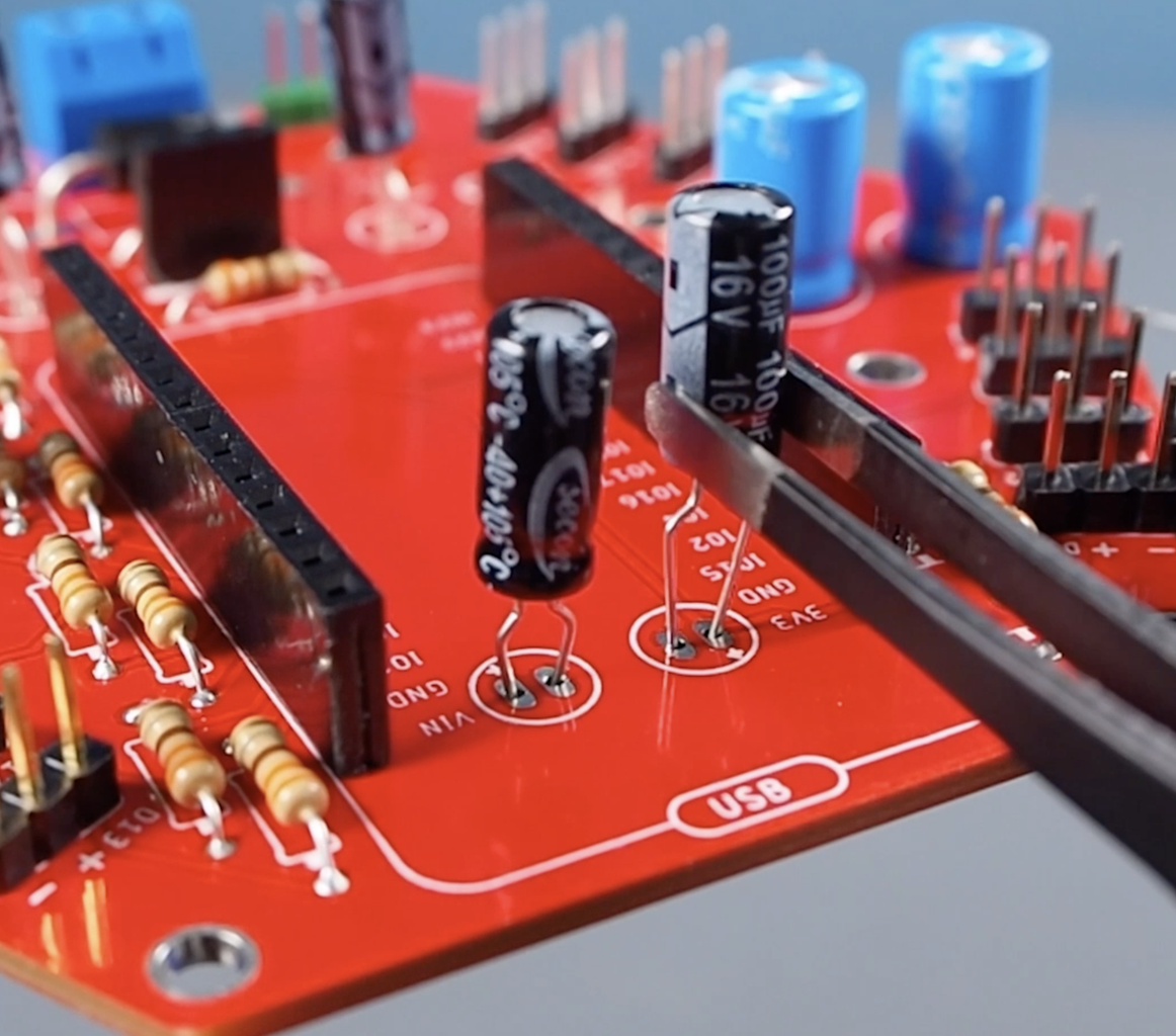
- Finally, place and solder the capacitors, then shorten the leg lengths.
Step 7: Uploading Code to the PCB and Testing Servo Motors

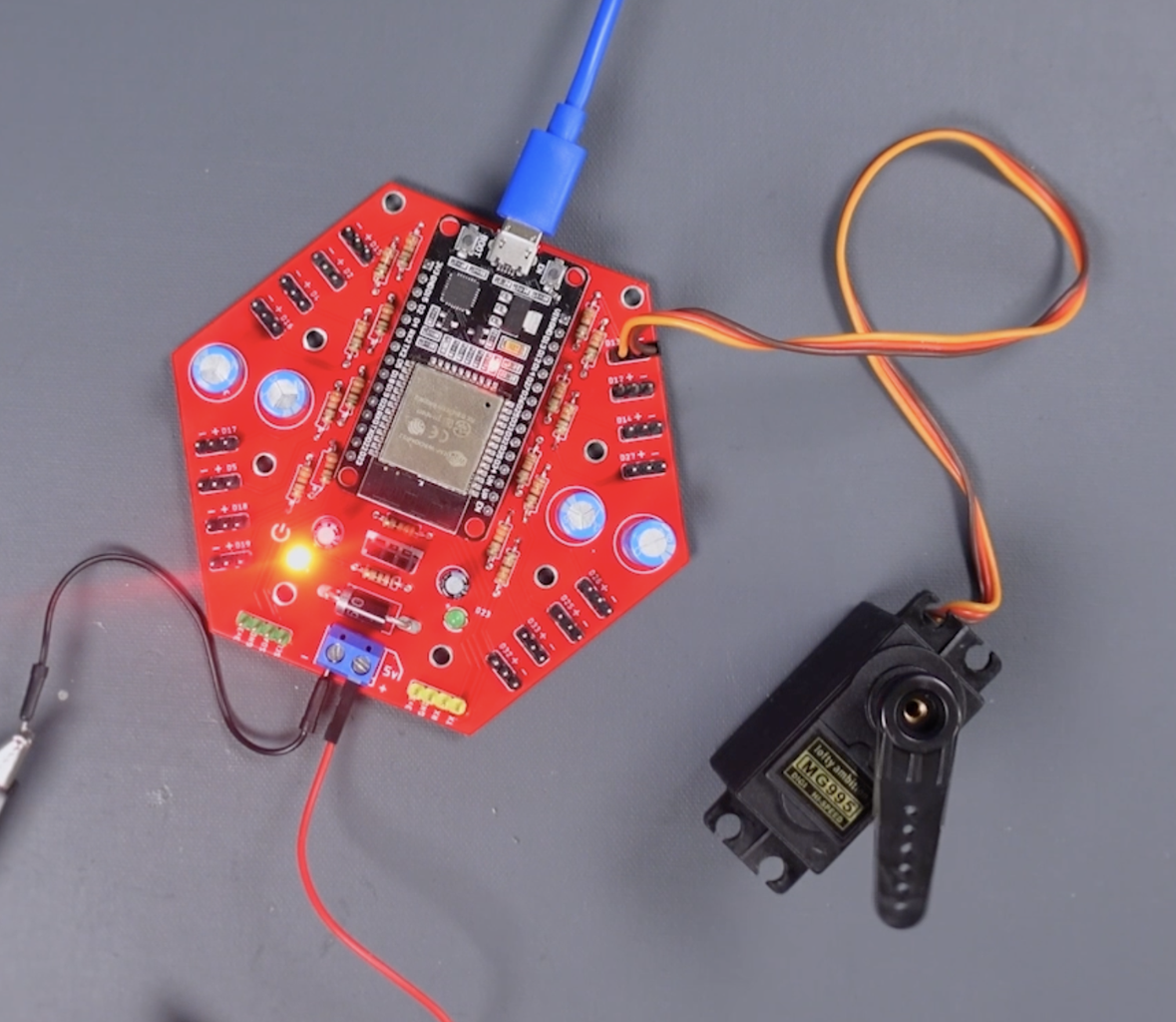


Place ESP32 on PCB, and connect the Servo motor to the GPIO13 input. The Simple Servo example is already uploaded. Let's supply 6V external power to the board and run the first test. The board is working great. The voltage regulator input on the board is empty, so the ESP32 is powered via USB while the servo motor is powered by an external power supply.
If you want to power the board with a single power supply, and the supply power needs to be higher than the 6V to 12V operating range, you should use a voltage regulator such as the L7805. However, if a voltage within the operating range of both the development board and the servo motor will be sufficient in your project, you can complete the power circuit using a jumper.
Step 8: Conclusion and Recommendations
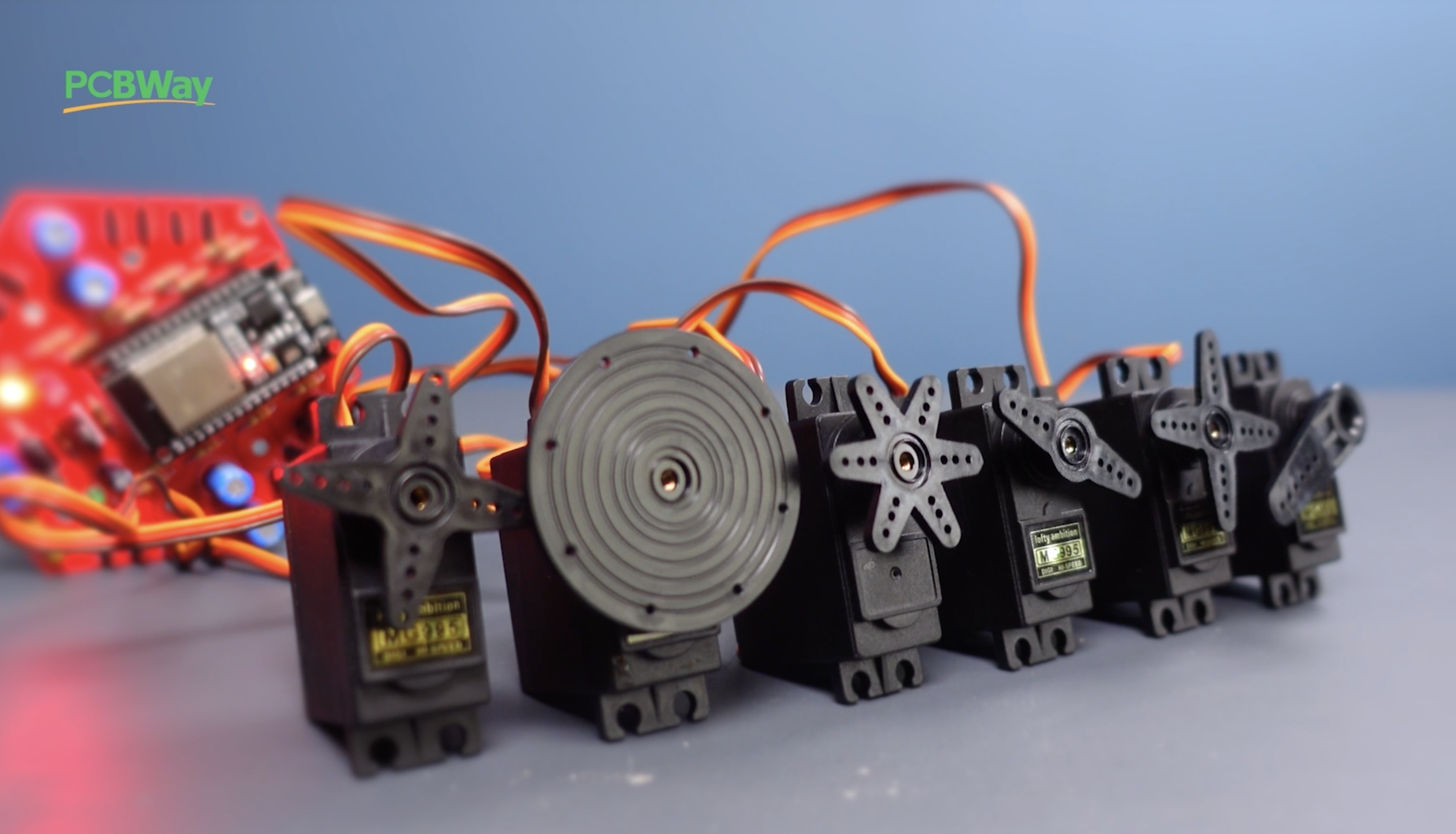


- 6 high-torque servo motors were connected to the board and 6 volts were supplied to the board. As you can see in the video, 6 high-torque servo motors were successfully run without any problems.
- This printed circuit board does not have any jitter problems and servo motors work stably.
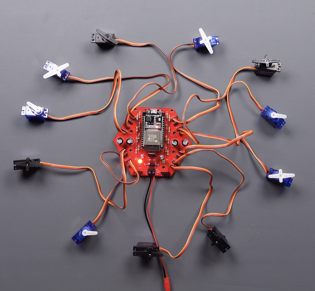
- In addition, the printed circuit board supports the control of up to 16 mini servo motors.
- A robotic arm with high torque servo motors was tested on this printed circuit board and worked successfully.
- ESP32 to ESP32 communicated with ESP-NOW, and as a result of the test, the board worked successfully.
- Connected to the board via Bluetooth using an Android app, and the board worked successfully as a result of testing.
As a result of all the tests, the servo motors moved toward the desired positions and without jitter. If you want to take a look at other projects that can be done with the board, you can reach them at this link https://www.instructables.com/ESP32-Servo-Motor-Controller-Board-Wireless-Contro/ and this link https://youtu.be/iuoqgFprUoE
Thanks for reading the project article. You can send your questions through the comments section, I will try to answer them when I have time.


