

Introduction: Optical Mouse Odometer for (Arduino) Robot


Accurately determining the progress of a wheeled robot can be pretty tricky (and expensive!). Dead reckoning assumes that our motors are perfectly matched, our wheels don't slip and the surface we are running on is perfectly flat: most of these conditions are unattainable and are never guaranteed. Rotary Encoders on the wheels or motors are more accurate, they certainly remove the need for matched motors and can deal with incline changes, however slippage is still an issue. Ultrasonic or Laser range sensors circumvent all of the mechanical issues that plague dead reckoning and encoders but require stationary fixed points of reference, are subject to interference (objects coming between the robot and the reference point) and have issues with regard to range, accuracy and resolution (the more you want, the more it costs!).
Ideally, we want a sensor that can accurately measure positional changes in two dimensions, has a simple interface, has low power requirements, is easily obtainable and cheap into the bargain. The solution: that old optical mouse you have lying around! Computer mice are designed to do just what we want: very accurately track the two dimensional movement of an object in near to real time. They actually have a resolution 1000dpi which means we are able to measure a movement of ~0.03mm in any direction!
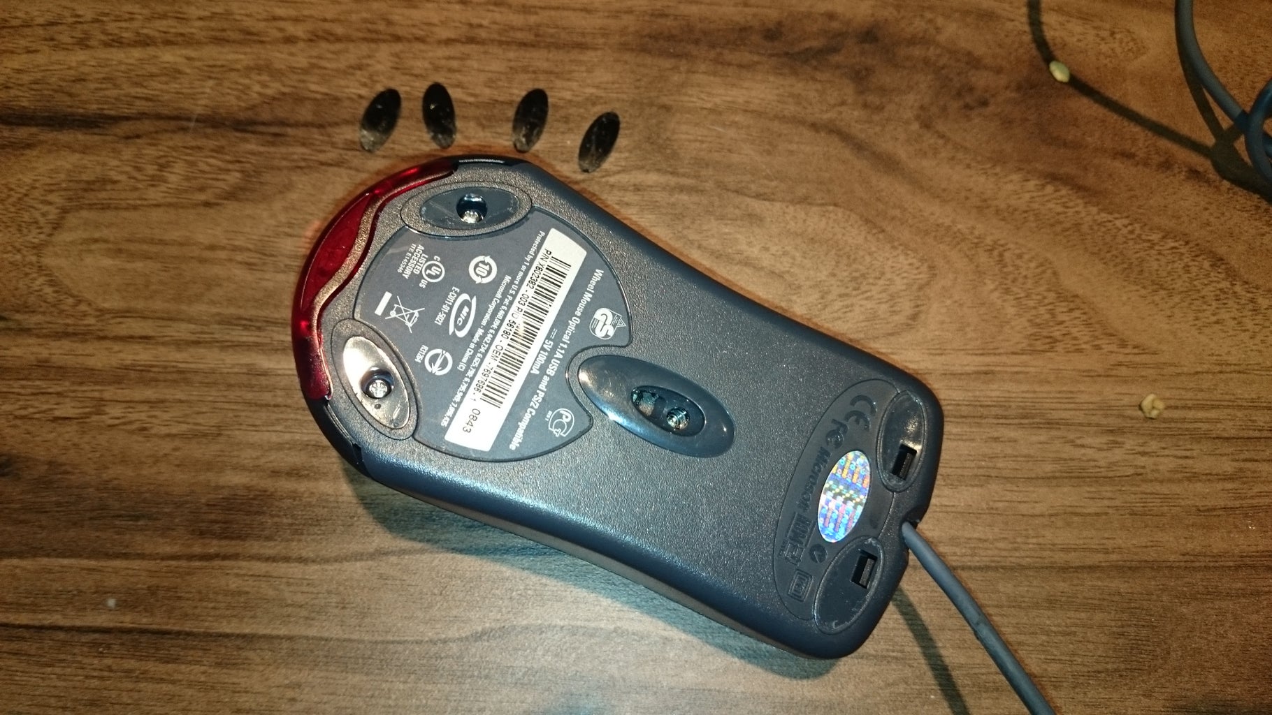
We do have to choose our mouse a little carefully however. We need one that either has a PS/2 connector (6 pin mini-DIN) or a USB mouse that is PS/2 compatible (should be stated on the bottom of the mouse somewhere, see picture). This is because the PS/2 protocol is really easy to implement (particularly for microcontrollers) whereas USB is somewhat more difficult!
I happened to have an old Microsoft USB1.1/PS/2 compatible mouse hanging around that I wasn't using, so I decided to sacrifice it to my robotical pursuits in the manner described herein.
Step 1: Tear Down


First things first, we need to open the case and liberate the electronic goodies within. I chose to do this because the mouse is far too big and bulky for my robot. If you don't want to this you just need a USB Type A or PS/2 socket that can be wired to the processor (Arduino in this case) into which the mouse can be plugged without modification, just skip this bit.
So, the process to deconstruct my mouse was as follows (also see pictures):
- Remove rubber adhesive feed covering screws (at the rear) and clips (at the front
- Remove the two screws at the back and then use a small flat bladed screwdriver to push back the clips holding the top and bottom parts of the case together at the front. (This may take a bit of fiddling, I actually inadvertently broke one of the clips in the process.)
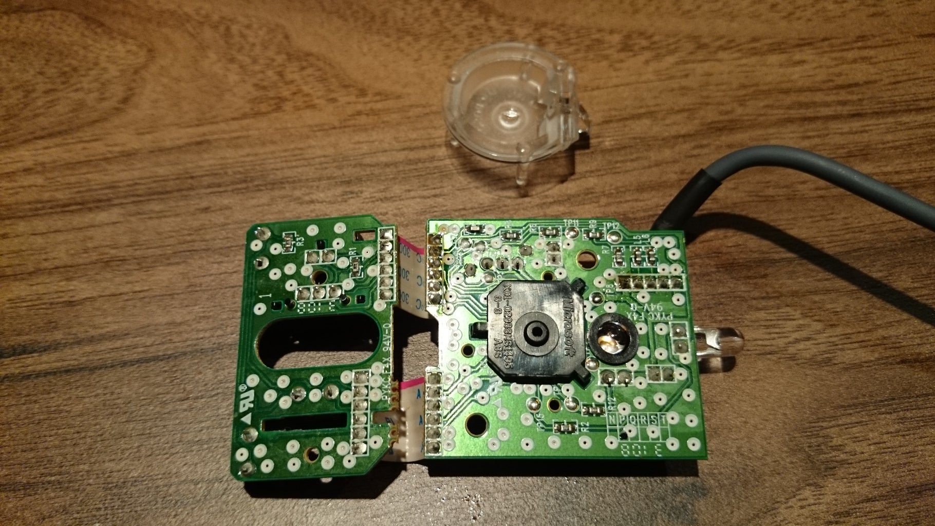
- Once the case is open, remove the scroll wheel and then any screws hold the circuit board to the case. There may also be a few small plastic clips that retain the circuit board. The small screwdriver used before and some wiggling should free the circuit board(s) from the case.
- There should be a clear plastic piece under the circuit board (the lens) which will also need, so retain this and the circuit boards, discard (or file!) the rest.
If you plug the mouse into a computer or laptop, ensuring the lens is correctly in place on the bottom, the mouse should work normally when you move it around.
Step 2: Initial Circuit Modifications


Now we've got our hands on the board we need to connect it to our microcontroller. To do this we can either use the existing cable (USB) in my case and wire an appropriate socket or we can replace this wire with some of our own. We also need to determine the function of each of our new wires. This is done simply by using a multimeters continuity setting and working out which connection on the board is connected to which pin on the USB (or PS/2) connector. The original wiring can be seen in the first image above and functions are, left to right, as follows:
- Red: Vcc (USB pin 1)
- White: Data (USB pin 2)
- Green: Clock (USB pin 3)
- Black: Gnd (USB pin 4)
- Black: Shield
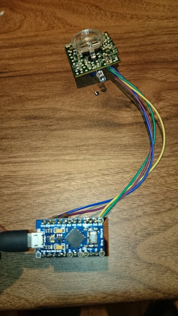
I chose to desolder the existing cable form the board and replace it with some wires with Arduino friendly Dupont connectors. I also chose not to connect a wire to the shield connection as its not strictly necessary. We then connect the mouse to our microcontroller of choice, an Arduino Leonardo Nano clone in this case, as follows:
- Mouse Vcc to Arduino Vcc
- Mouse Gnd to Arduino Gnd
- Mouse Clock to to Arduino Pin 6
- Mouse Data to Arduino Pin 5
Step 3: Software
Now we've connected everything up we need some software for the microcontroller. Firstly we need some code that implements the PS/2 protocol. Helpfully there is an Arduino library available for this, however I found it to be a little outdated and I wanted to add some new functionality so I reimplemented and extended it a bit and it can be found here: https://github.com/jazzycamel/PS2Mouse.
The library contains a simple example sketch (PS2Mouse.ino) which requests the mouses status and position delta (the change in X and Y directions since we last asked) and prints it to the serial port once every second. If we program the Arduino, and everything has gone well, the mouse will light up and your favourite terminal application (or the Arduino IDE's serial monitor) will show a stream of status, X and Y deltas once a second. The X and Y data has a (theoretical) range of -255 to +255 and each step (theoretically) represents 0.25mm which means we can (theoretically) measure up to 63.75mm change in any direction (for X positive values are to the right, for Y positive values are forwards).
Note: the above numbers are theoretical for the following a reasons:
- Whilst a mouse can report the range -255 to 255, so far all the mice I've used only return -128 to 127.
- Whilst each step supposedly represents 0.25mm, I've found this to be very dependent on the mouse and the surface its on. Generally the step size seems a lot smaller.
Step 4: Further Modifications and Finishing Up

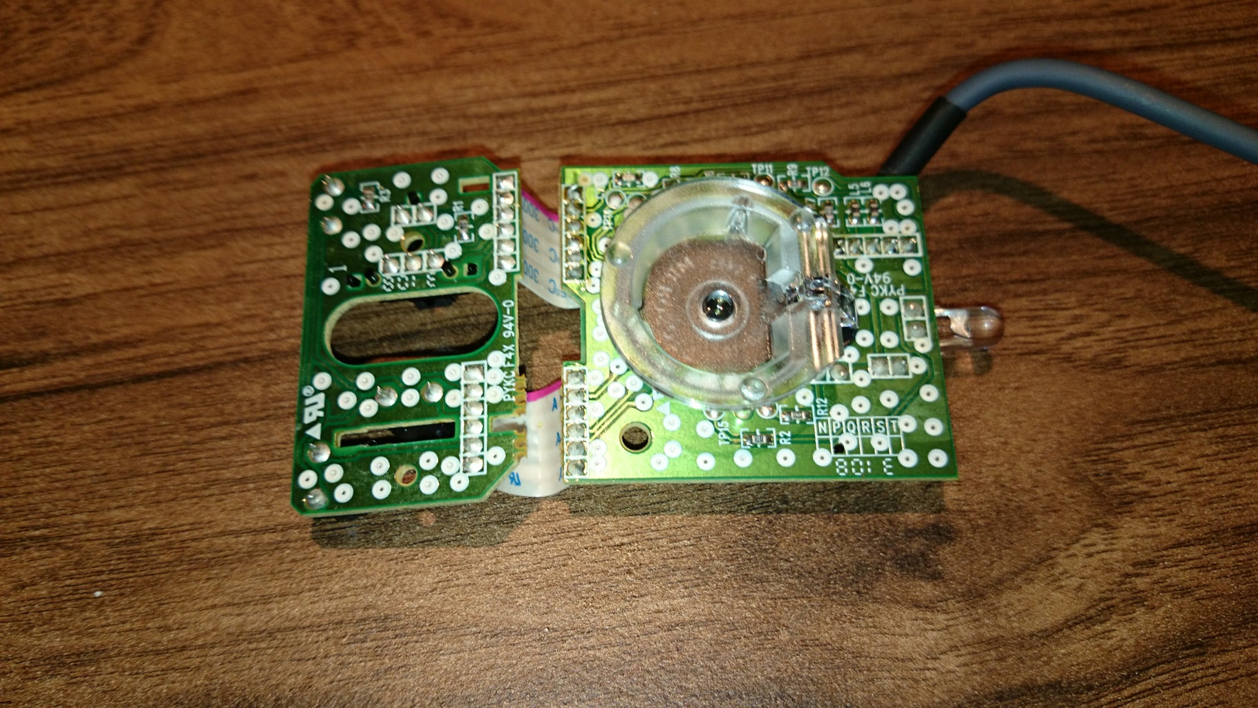
Once I'd got everything up and running I decided to remove the extra circuit board which has the electronics for the mouses buttons and scroll wheel as I didn't need these features and they were just taking up space. I desoldered both of the ribbon cables, plugged everything in and... nothing. The mouse wouldn't light up and I got nothing from the serial port. A little investigation with the multimeter told me that three of the pins (1,3, and 6) on the rightmost connector (looking from the top) were usually connected together when the button board was connected, so I just shorted them together with some scrap wire as shown in the picture. I then plugged everything back in and Hey Presto! We were back in business!
The final touch was to superglue the clear plastic lens in place on the circuit board to retain it and so I wouldn't lose it.
The next step will be to mount this on my robot and put it to use. I actually intend to cannibalise another mouse in the same way and fit both to the robot so as to be able to accurately determine orientation as well as progress (as described here).
I hope people find this little tutorial useful, please feel free to ask any questions. Thank you.


