

Introduction: P10 LED Display WiFi Controller Board (ESP8266, MQTT)


In this project, I will show you how to wirelessly send scrolling text to P10 LED display using ESP8266 module, MQTT and smartphone. It is an "Internet of Things" project, a display connected to a WiFi network using ESP8266 module and data communication between this LED display and a smartphone using the MQTT protocol. The PCB I designed combines the ESP8266 module and the P10 LED display, allowing you to control this display over WiFi. In this project, you will see how to solder the PCB, programming it and then use it in your project to display the messages or images you want on the LED display. Let’s make it!
Step 1: How It Works?
In this project, it is connected to a WiFi network using an ESP8266 module and communicates with a smartphone with the MQTT protocol. MQTT (Message Queuing Telemetry Transport) is an internet of things (IoT) protocol and allows sending and receiving data from one device to another. In this project, the ESP8266 device connects to the MQTT server and receives the text sent by the smartphone.
The P10 LED display is a multi-dot LED display, and text and pictures can be displayed. In this project, the text received by the ESP8266 device is printed on the P10 LED screen. This project allows you to learn how to communicate data between a smartphone and a device using IoT technology and how to write on the P10 LED screen.
Step 2: Printed Circuit Board


I designed a Printed circuit board for this project and ordered it from PCBWay. Why not a breadboard circuit? Because breadboard circuits are ideal for testing and running small-scale designs, they are not durable for long-term use. Printed circuit boards, are used to design electronic circuits more durable and stable for long-term use. If you want to have this PCB, you can get it from this link - https://www.pcbway.com/project/shareproject/P10_Display_WiFi_Controller_Board_ESP8266_MQTT
Step 3: Components and Using Stencil


Some "surface mount device" ie SMD components are preferred in this board, this affects the size and cost of the board design. For the assembly of SMD components, a stencil is generally preferred. Solder stencils help to accurately apply solder paste in position of components and the stencil is usually ordered with the PCB. This process is simple, first fix the printed circuit board and place the stencil to match the board. Then put some solder paste on the stencil with the help of a spoon and spread it with a spatula.
- 5x Resistor 0805 10K Ohms
- 1x Resistor 0805 1K Ohms
- 1x Diode Schottky SS36 3A 60V
- 3x Capacitor 0805 100nF 50VDC
- 2x Capacitor 100uF 16V 6.3x5.7 BXJ16VC100M
- 2x Switch Tact 4.2x3.2MM 434123025826
- 1x Voltage Reg 1117 3V3 LDO SOT223
- 1x LED 0805 Blue
- 1x Terminal Block 3.50MM 2P
- 1x ESP8266-12E WiFi Module AI-Thinker
- Female and Male Header
Step 4: Place the Necessary Components on the PCB


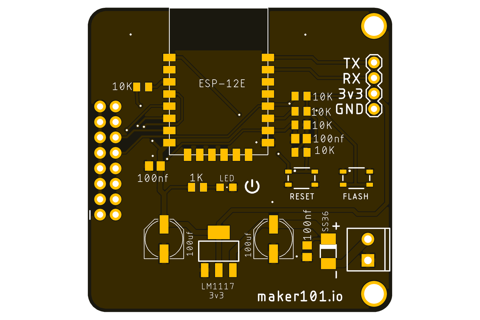


After applying the solder paste, it is necessary to place the required components on the PCB. Where to place these components is usually indicated by a designator or footprint reference. These references are used as part of the PCB design and ensure the correct placement of components. Designator shows what a component is and where it is located. For example, a resistor's designator starts with a number such as "R1", "R2", which indicates the resistor's position on the PCB. A footprint specifies the physical dimensions of a component and the locations of its ports.
Step 5: Soldering


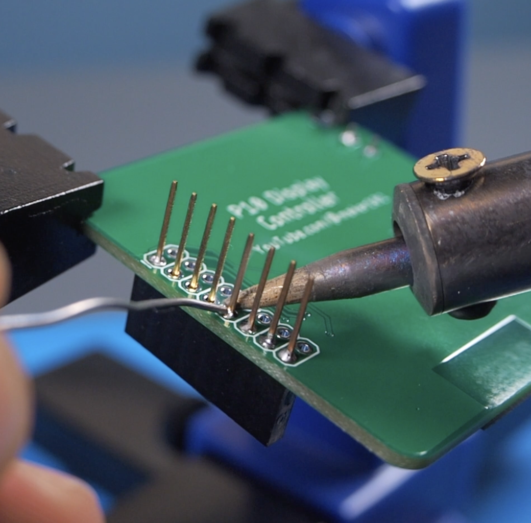

After the components are placed on the solder pads with the help of solder paste, the soldering process begins. Soldering is usually done with a hot plate machine or a hand soldering iron. The soldering machine heats and melts the solder paste and fixes the components in place. After the soldering is complete, the components are completely fixed in place when the solder paste has cooled. After soldering a few more components, the board will be complete. These components are a few headers and a screw terminal block. It can be easily soldered with a soldering iron.
Step 6: Programming


MQTT
Now it's programming time, grab a cup of coffee! The MQTT protocol is a messaging method that facilitates data communication. In this method, data is shared between devices through a server called "Broker". "Broker" is an intermediate server that will provide data communication between your smartphone and the ESP8266 device. You can use an MQTT broker like Mosquitto or HiveMQ. Devices are connected to the Broker by naming a "Topic" and send and receive data over this "Topic".
- MQTT Broker - https://www.hivemq.com/public-mqtt-broker/
- MQTT Client Library - https://www.hivemq.com/mqtt-client-library-encyclopedia/
Library
Although this method of communication sounds complicated, we will use a library shared by "Ronin" that makes it easy. Download library from shared link and open source code with "Arduino IDE". It is enough to enter the network connection information and MQTT parameters in the code. If you are going to program an ESP for the first time, install the ESP8266 from Board manager and go to settings and add the shared URL for the ESP8266. Finally, you need to install the "Client" library used in the code.
- Source Code and Library - https://github.com/byronin/MQTT-DMD/tree/main/Lib%26Software
- ESP8266 package link - http://arduino.esp8266.com/Arduino/versions/2.0.0/doc/installing.html
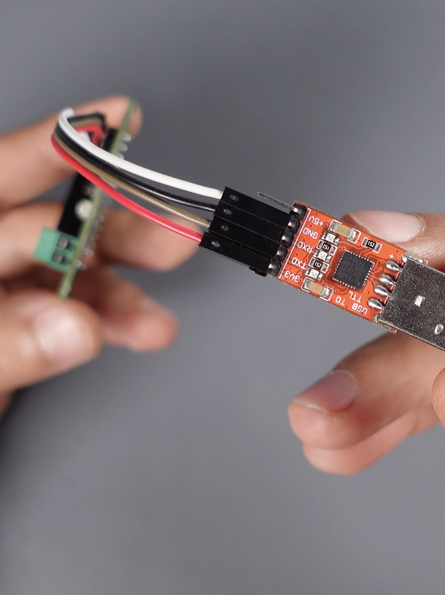
USB to TTL
If the code is ready, let's move on to the installation part! A USB converter is required to program the ESP8266 modules. USB to TTL converters are used to connect to the ESP8266, program it and operate the device using serial communication. Connect the board to the converter and connect it to the computer. The important point here is that it should be fed with 3.3V. A one-time process must be taken when using the ESP8266 for the first time. Press the "Reset" and "Flash" buttons at the same time, then release the "Reset" button first, then the "Flash" button. This will make the ESP8266 ready for code. After this process, you can upload the code by selecting the port.
Step 7: P10 LED Display and Application


P10 LED displays are generally used to design outdoor or indoor LED display panels. The P10 screen size is 32 by 16, which means there are 32 LEDs in each row and 16 LEDs in each column. That is, each panel unit has a total of 512 LEDs. There are 3 ports on the back of the P10 screen. One of the ports is the pin inputs for the microcontroller, the power inputs in the middle, and finally the port used to connect more panels together. Each panel needs 5 volts, also 5 volts is required for the ESP8266 controller. I created a common line for both. Meanwhile each panel needs about 3 amps. Then connect the common ground line. When the screen is powered on, the welcome message specified in the source code will be displayed first.
Now let's take a look at how to print text wirelessly via MQTT! There are several MQTT tools for this, I will control it via an android based smartphone. MQTT client tools for different platforms to help you quickly get started with MQTT application development and testing - https://www.hivemq.com/mqtt-toolbox/
It will be enough to install the application on the phone and enter the necessary parameters and run it. There are 2 important points here, the first is to depend on the network parameters specified in the code, and the second is to enter the "Topic" parameter specified in the code. Now you can print the scrolling text on the P10 screen by entering the desired message. Please don't forget to follow and hit the like button for more content! Thanks for reading.

Participated in the
Anything Goes Contest


