

Introduction: Partner-calling Wifi Lamp Duo (arduino Based)


This is a pair of desk lamps, powered by an Arduino-based microcontroller, with a custom engraved acrylic sheet, and a 3d printed case.
My wife and I needed a way to call each other in the house without disturbing the kids, the meetings we were in, ourselves, and without having to figure out where the phone was.
With these lamps, each of us has one on the desk or the room we are in. All you need is a press of a button on your side, and the partner's lamp will illuminate in purple, while yours will be yellow. Then the partner will push the button to acknowledge your call, and your own lamp will illuminate green.
The caller can reset both lamps with an additional press of a button.
They work on your existing wifi, and require to be connected to a usb power source (1 amp should work) via a microusb cable.
I've learned a lot while building this project, and so I thought I'd share also the DON'Ts. You'll find them as "Optional reading" sections. You can skip those sections if you like.
I'm submitting this Instructables to the 2022 Lamp contest :)
Supplies
You'll need a few items, and some tools. You may be able to replace a few of these.
Bill of materials:
- 2 x Wemos D1 Mini clones (I used an old version, similar to these) Note: Aliexpress now mostly sells updated versions of these. Make sure you go for the ESP8266
- 2 x protoboards (I used two from this Elegoo bundle, which I highly recommend)
- 2 x 8-bit ws2812b rigid strips (this is a 10-unit pack)
- 2 x pushbuttons (I used two from this bundle)
- 2 x microusb cables (I had spare ones at home)
- 2 x acrylic rectangles, which you can cut from a larger acrylic sheet. In general, you can use any acrylic sheet to start from, I've used a clear 5mm acrylic, similar to these
- Optional: assorted breadboard wires (I used some from this pack)
- Optional: assorted arduino headers (I had some spare ones, your d1 minis should come with everything you need)
Tools:
- 3d printer, or access to a 3d printing service. My own cost for printing all the parts was around 2 euros. I am not sure how much an external service would charge.
- Something to cut the acrylic. After trying several ways, I've found that using an oscillating multi-tool, with semi-circular blade is the best option (see pictures below).
- Soldering iron and solder.
- A dremel with metal wire rotating tip
- Sanding block, with 120 or 180 grits
Additional requirements, found in this Instructable:
- Arduino code
- STL files to print the case
Total cost of the project depends on what you have already from the above, and how you consider the cost of the bundle. If you need to start from scratch, and you buy all the bundles above, it will be in the region of 40 euros. If you only consider what you use from the bundles, then it's less than 10 euros for both lamps.
Step 1: Putting Together the Electronics


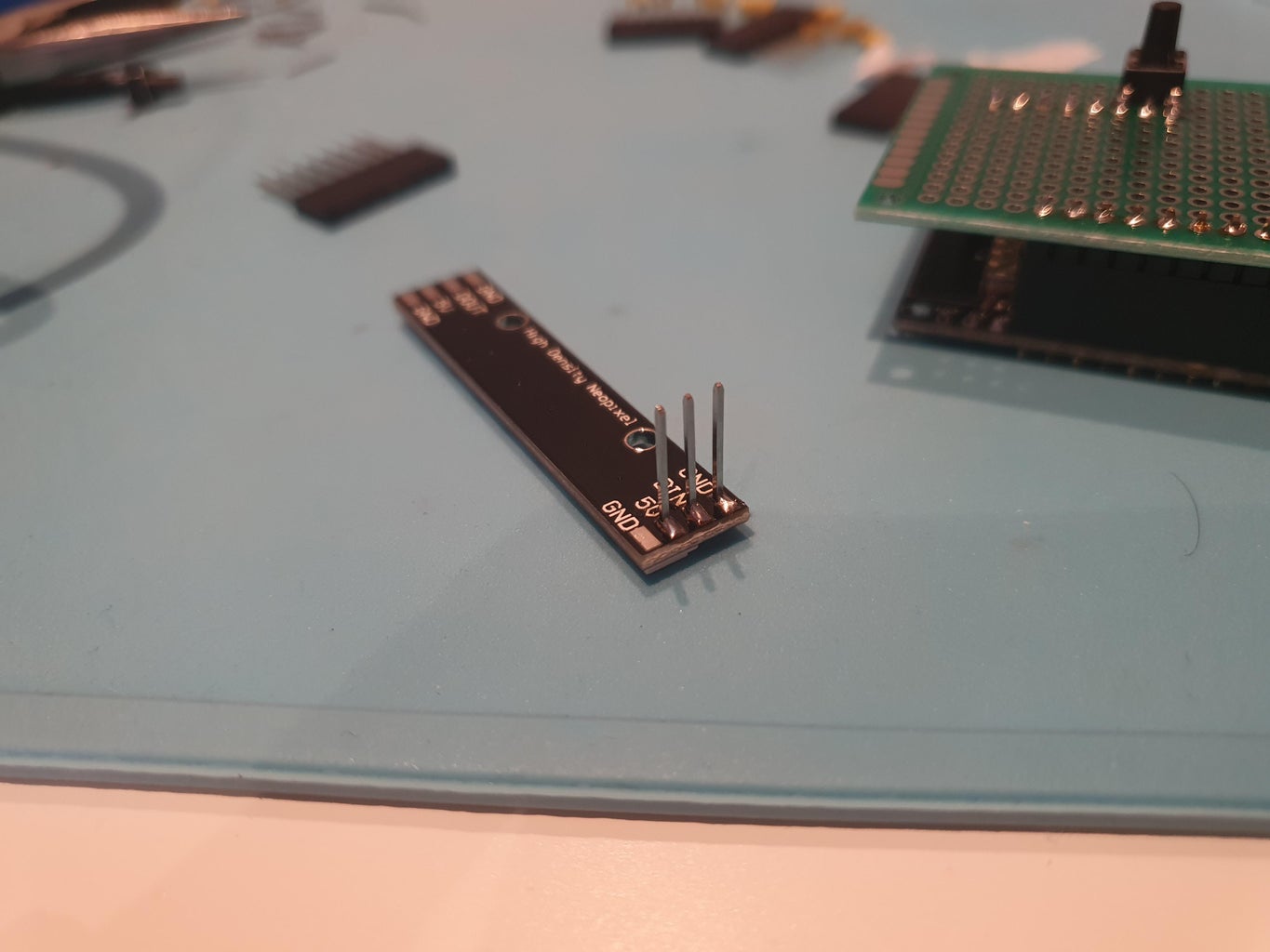


In this step, you are going to create a circuit like the above. There are a few discussion points.
First, we are wiring the pushbutton on ground and D5. Pushbuttons with 4 pins are actually pushbuttons with 2 pairs of 2 connected pins. Choose one side of the pushbutton, and work on those two pins only. Second, the better way to wire the pushbutton would be on ground, voltage, and resistor. However most Arduino compatible microcontrollers have integrated pull up resistors that can be leverage from the software. That's what we are going to do.
Second, I've tried a flimsy circuit with all the above, without the support of a breadboard, or protoboard, or custom pcb. The result was very unstable, and so I opted for using a protoboard, 4 headers (2 female on the D1 mini, and 2 male on the protoboard), and lots of soldering and protoboard wires. However complex my wiring was, the circuit I've put together is the same as the above schematics. I just needed to wire the connections through the holes of the protoboard depending on where the pins were (if above or below the board). That resulted in a lot of painful soldering.
Caveat: make sure you solder the header on the D1 mini with the above orientation, otherwise the 3d printed parts won't fit.
Step 2: Optional Reading: How to NOT Assemble It
You can skip this section if you don't want to learn from this mistakes.
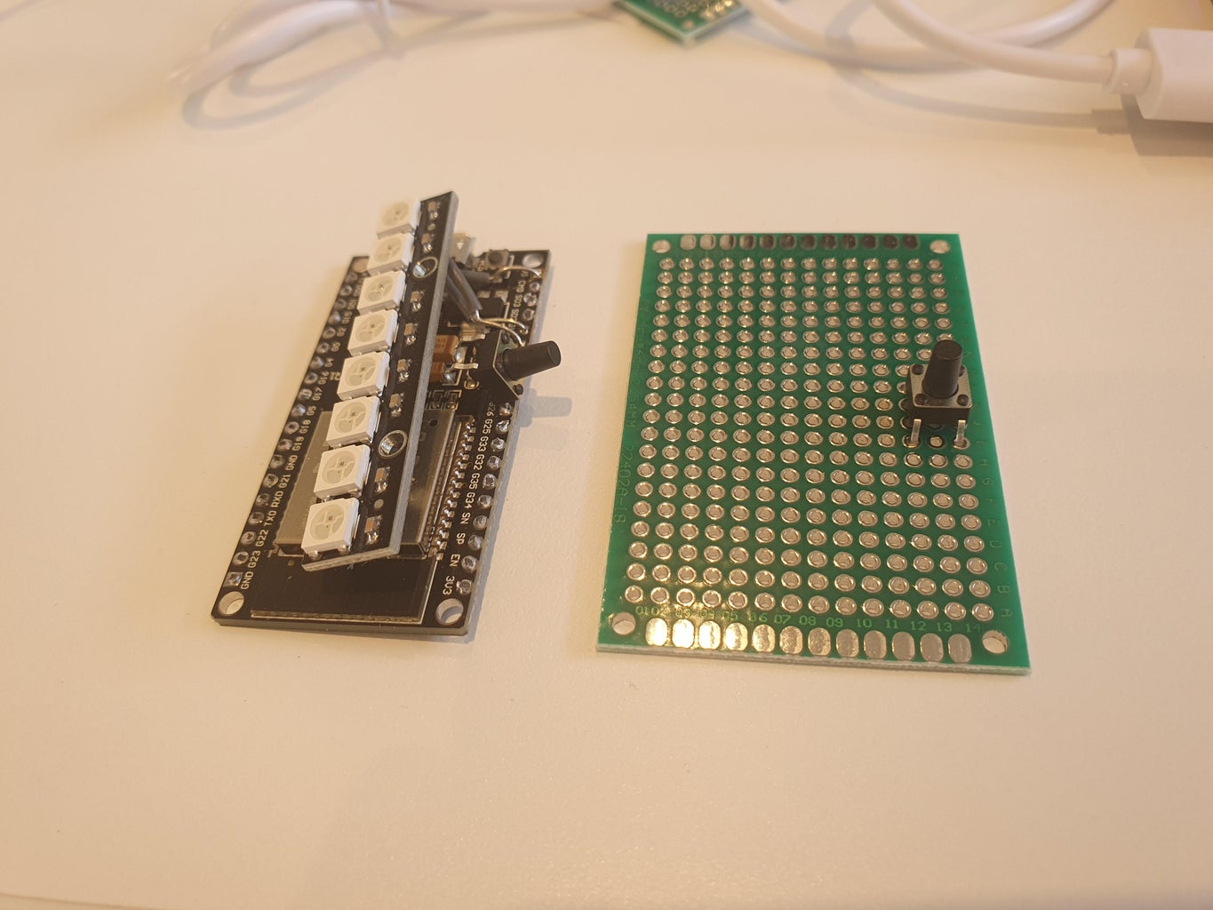
I had initially used an ESP32 board, instead of the Wemos D1 mini. It resulted to be overkill, so I switched to a D1 mini. But the purpose of this image is to show you how NOT to proceed with this project. The connections above worked, but they were extremely flimsy, and would have required me to project a lot of 3d printed parts to barely fix it.
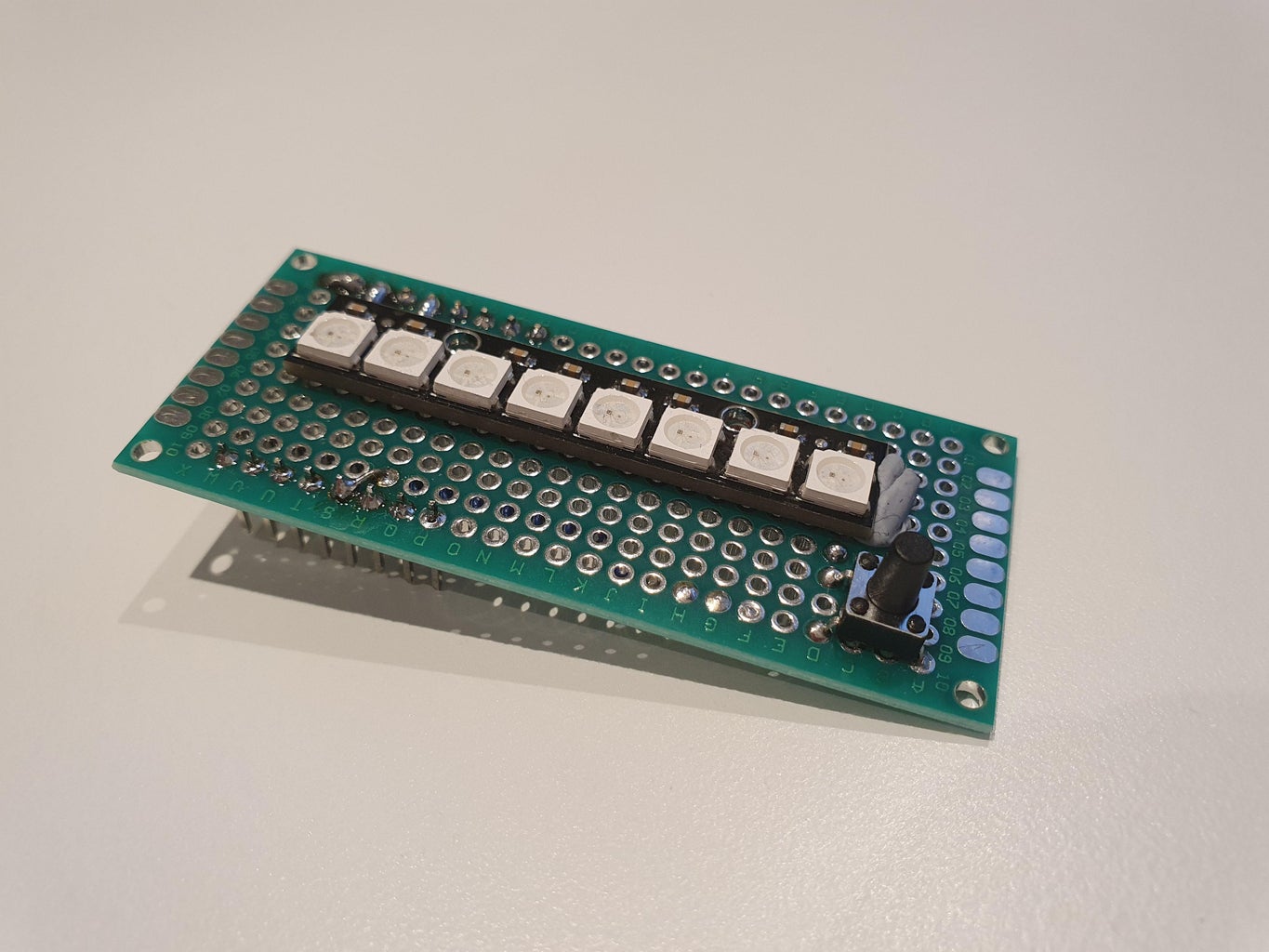
This is were I've trashed everything (saving only the led strip) and started fresh, with a smaller protoboard, a Wemos D1 mini, and lots and lots of soldering.
Step 3: Program the Microcontroller
The attached .ino file implements the entire protocol. When opened in your Arduino IDE, you'll see a few defines to adapt to your case: wifi and password, static ips, MAC address of one of your two D1 mini.
This code implements basically three tings:
- a wifi connection and communication protocol
- LEDs management
- pushbutton management
Let's see them in details.
As wifi and communication protocol, I've considered 3 options: a) ESPnow protocol, that creates its own network between the two ESPs (works with both ESP8266 and ESP32); b) connect to existing wifi and communicate directly exchanging bytes via sockets; c) connect to existing wifi and implement http server and client.
Option a) has a couple of advantages: it doesn't need you to setup IP addresses, and it easily scales to multiple lamps. However, it doesn't work on my case. You see, we have an attic which has an insulation foil on the floor, which blocks wifi. To bring wifi to the attic, I've run an Ethernet cable upstairs and added a router there. The only way to communicate between attic and rest of the house is via the router. The two microcontrollers won't be able to see each other through the foil. So I've discarded a).
Between b) and c), I just went to c) for the elegance of the solution, and because I had lots of code that I could reuse from past projects. So option c) it was.
The code sets up a webserver, and three handler functions, for handling the "I've been called" event, the "I've been responded to" event, and "I've been requested to reset" event. On the other way, it just connects as a client to the receiver's handlers.
To connect to the existing wifi, again I've considered two options: setting up static IP addresses (either on the microcontrollers or on the routers), or getting a dynamic IP and perform a discovery. The discovery would scale much better, but for my case, setting up a couple of addressed wasn't a big deal.
To use only one copy of the software, each lamp needs to figure out which IP to use. This is done by hard-coding the MAC address of one of the two microcontrollers (after having printed it on the SerialMonitor), and checking if one lamp corresponds to it or not.
Handling the LEDs is pretty easy. A part for the flashing red animation at the beginning when we connect to the wifi, we just need to fill the strip with a color (yellow=I've called, purple=I've been called, green=I've been responded to). You can play with colours and brightness to your liking.
Handling the pushbutton is actually trickier. You might be tempted to just digitalRead on the input pin. This would be kind of possible with the better wiring of the pushbutton (vcc, ground, and resistor), as the resistor would clean the output. With the internal resistor, the output if very bouncy, so we need to debounce. This is done by checking for how long the status of the button is changed, before trusting the signal. I've copied the example from the Arduino website, which suggests 50ms as timeout, which seemed reasonable to me.
Attachments

Step 4: 3D Printing
I'm including here 3 different versions of a custom pushbutton cap. The reason for the multiple versions are basically pushbutton model, and printer tolerances. The 0.35mm inner hole works well with my setup.
I've printed the base with 0.30mm layers, basically in draft, and 10% infill. There is no need for a better print, in fact you do want the rough layers for having a bit of friction with the top, so the lamp doesn't open easily.
The top deserves some discussion. I'm using PrusaSlicer as slicing software, which has the "gyroid" infill pattern. Set that up, and print with 40% infill. Less than this (or a different pattern), and you may see the light through the top plastic.
If you don't have the gyroid in your slicing software, maybe go with 60% infill. The top is best printed at 0.20mm layers.
My first layer is setup to be supers smooth, so I also add a 0.7mm elephant foot compensation in PrusaSlicer to make sure all parts fit well together.
You can print the heart (cuore) with the settings you wish. I printed it with 0.20mm layers.
I'll add also the editable object files asap.


Step 5: Cutting the Acrylic

Here, we need a few steps. With the above printed heart template, we need to carefully take the measurements on the acrylic sheet. I've gone a couple of mm over, so basically placing the template on the acrylic, marking its contour with a marker, and following the inside of the marks. This left me with 2mm all around to play with some sanding.
To cut the acrylic, I've used an oscillating multitool with a semicircular blade, the one you use for levelling your cuts. It's a fantastic way to cut it, for a couple of reasons: first, being very large, it disperses heat very well and doesn't melt the acrylic. Second, you can use it before sanding to level your cuts faster.
After cutting, use a rigid sanding block (don't use sandpaper without a rigid support, otherwise you'll end up with a very wobbly contour), with a suitable grit. I've preferred to work more, but go easier, so I've used 180. I think 120 should work just fine. I wouldn't go under 120. Remember your best result is with a frosted contour to diffuse light, not with a shiny one.
Step 6: Frosting the Acrylic

Place the heart template on the cut-to-size acrylic (it should be a snug fit, but without distorting the template). If you have used a 5mm acrylic sheet, the template will be half a millimeter shorter on purpose, to avoid touching the table and moving the acrylic.
The best way I've found to frost the acrylic is with a wire rotating bit and a dremel set at half speed. As I'm using a cheap dremel, it's possible my half speed is much slower than a branded Dremel half speed. In doubt, start slower.
Do not apply pressure, you want to "brush" the acrylic, not scratch it. Follow the inner contour of the heart, then proceed on the inside. Repeatedly rotate the heart after one pass on one orientation, to make the frosting a bit more uniform.
The last pass anyway will leave the final marks. Decide on the last pass final speed and pressure with the dremel. You can also play around and make some intentional Michelangelo-style "unfinished" rougher touches. It's down to your taste.
To clean the acrylic, DO NOT brush off with your hands. Just use water from the tap and gently help the acrylic sand away, otherwise you risk scratching the rest of the acrylic.
Step 7: Optional Reading: How NOT to Cut the Acrylic

You can skip reading this step if you don't want to learn from my mistakes.
In the past, I had used the straight blade of the multitool to cut the acrylic. It worked on the LED-specific grey acrylic. For some reason, this sheet was melted on the sides when going this way. So I've tried a manual saw, but it was taking ages.
Step 8: Optional Reading: How to NOT Frost the Acrylic


You can skip this step if you don't want to learn from my mistakes.
Initially, the plan was to print the heart template on adhesive paper, stick it to the acrylic after cutting the heart, and then sanding manually to frost. No way. First, it's impossible to cut the adhesive paper and remain with a clean contour. No match for a 3d printed template. Second, I've tried sanding manually with a sanding sponge, and with a powertool, a Black&Decker Mouse with the 180grit detailing tip. The contours were terrible, the inside was not uniform, and the Mouse had damaged the template going outside of the heart.
So I went with the 3d printed template. But then what? I've got two people advising me to use acetone. It was counterintuitive, as I was expecting the acetone to smoothen, not frost, the acrylic. But I've tried nonetheless. Zero result, nothing at all. I suspect nail polishers contain very small percentages of acetone and this is the result.
Then, on the failed acrylic, I've tried several dremel bits, including the ones for carving and grinding. They were either too aggressive, or the would skid on the acrylic, making the frosting a bit spotty.
In this comparison image, you can see all the failed attempts on the right heart, and the final result on the left.
Step 9: Putting It Altogether


If you've come so far, you'll really enjoy this step. It takes 10 seconds to assemble everything, and everything was a snug fit for me. If this is not your case, check you printer's tolerances and adjust for them.
The advice is to put the button cap *after* the top, but I've done the opposite here, to check the tolerances for the hole.
For demo purposes, I haven't glued anything. To be honest, the case doesn't need any glue, nor does the button cap.
The acrylic is pretty loose instead. If you don't like this, you can add some hot glue all around the base of the acrylic before inserting it, or some BlueTack from the inside should work just fine.
Enjoy the final result!
Step 10: Possible Extensions
There's a few things I'd like to add / try from this result.
First, scale up the network, and add discovery of other lamps. In this way, I can have one lamp in each room, and one lamp will call all other rooms. It will require two for loops in the code, one for the discovery, one for the communication.
Second, I'd like to add a buzzer. I know, I said it should not be disturbing anyone. But perhaps it could buzz once every 5 minutes as a reminder.
Third, I'd like to experiment more with the acrylic frosting and carving. With the right combination of pressure, you can actually vary the intensity of light diffusion and make some detailed drawings.
Any additional idea, please let me know in the comments!
Thanks!

Participated in the
Lamps Challenge


