

Introduction: PetCurfew II: an Automated Cat Door Featuring the Photon and IFTTT


This is a followup to my "Pet Curfew: An Arduino Controlled Pet Door" instructable published a few years ago in which an Arduino Nano, real time clock and servo were added to a small cat flap door to restrict the hours during which our cat was allowed to go out. Although it still works 3 years later, it is time for an upgrade.
We are going to add internet connectivity to the door using the latest processor from Particle (formerly Spark) called the Photon. The Photon is a development board that uses a ST STM32F205 ARM Cortex M3 microcontroller (with 1MB of flash and 128KB of RAM) running at 120MHz coupled to the popular Broadcom BCM43362 802.11b/g/n Wi-Fi chip.
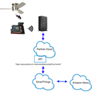
To achieve Internet of Things (IoT) status, we will leverage the Particle Cloud and the IFTTT (If This Then That) web service to check the status of our cat door or to open/close it remotely.
Let's get started.
Step 1: You Will Need...


- A Photon from Particle $19
- A 5V USB power supply with a USB Micro B connector $8
- A servo $15
- A couple of Momentary Roller Switches
- A couple of momentary push button switches
- 4x 100nF (0.1uF) capacitors
- A 220 Ohm resistor and a green LED
- A PetSafe (Staywell) Manual 4 way deluxe locking cat door PPA00-11325 $33
- Epoxy glue
- Miscellaneous nuts and bolts (typically used in PCs)
- Four N52 grade strong magnets
- Breadboard wiring
Tools:
- Philips screwdriver
- Dremel tool
- Power drill
- Soldering iron (optional)
Step 2: Install the Roller Switches


The two roller switches will be used to monitor the door opening to the outside and to the inside.
Install the breadboard in the wall mounted part of the door and center it.
Cut out the location where the first switch will be installed, to the right of the breadboard on the wall frame. Epoxy glue one roller switch. It will monitor the cat going out
Cut out the location of the second roller switch at the center of the inner frame. Epoxy glue the second switch.
We will connect later the "cat going out" switch to pin D3 and the "cat coming in" switch to pin D2. The other connector on each switch will be wired to ground. Because the Photon has built in pull up and pull down resistors, we do not need to add a resistor when connecting the switches.
Step 3: Install the Push Button Switches and LED to the Top of the Wall Frame


Drill a couple of holes to the left of the breadboard and attach the push button switches using the flat nuts that came with the switches. Drill another hole for the green LED next to the switches.
Solder or attach solid wire to each terminal of both push buttons and LED. The wires need to be long enough to plug into the breadboard.
Step 4: Install the Servo


This is probably the hardest part of the project as we will be cutting several holes in the outside frame to install the servo.
Measure the servo and outline its dimensions on the frame, making sure the servo hub is centered at the bottom of the door. Using the Dremel tool with a cutting saw, carefully cut out the template. Add a notch to accomodate the servo wires. Epoxy glue some of the material that was removed to level off the area where the servo will be mounted. After marking the 4 posts location, drill the holes.
Bolt the servo in place and attach the "super strength" servo arm. The servo arm needs to be positioned so that it is at 0 degree when in the closed position and at position 90 degree when retracted (open position).
Position the flap on the door. Mark the flap and cut it so that the flap closes freely around the servo.
Finally, with the arm in place, cut out a notch in the wall mounted frame so the servo arm can travel freely from the retracted position (90deg) to the closed position (0deg).
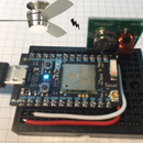
Step 5: Connect Photon and Wires to the Breadboard


Install the Photon to the left side of the breadboard to allow for routing of the USB cable.
Connect the switches, push buttons, servo and wires to the breadboard using the Fritzing schematic.
We will connect the "close door" button to pin D5 and the "open door" button to pin D4. The other connector on each switch will be wired to ground. Because the Photon has built in pull up and pull down resistors, we do not need to add a resistor when connecting the switches.
Connect the 220 Ohm resistor to PIN D5. Next connect the green LED anode (longer wire) to one side of the 220 Ohm resistor on the breadboard. Connect the negative wire to the ground on the breadboard.
Connect the servo yellow wire to D0 and the black and red wires to ground and power respectively.
Route the wire as shown in the picture.
Update: You will need to connect a 0.1uF capacitor to each of the 4 switches in order to avoid getting spurious readings, which I was getting on a random basis once or twice a day. The + side of the capacitor connects to the pins (D2/D3 and D4/D6) and the - terminal connects to ground.
Step 6: Software
Now for the fun part. Fire up the Particle web IDE and follow the registration steps for your Photon. The steps can be found here: https://docs.particle.io/guide/getting-started/sta...
We will assume that your Photon is now connected to the Cloud via you Wi-Fi access point.
We will need to know how to do several things for this project:
1. Reading a switch or push button
The mechanism for reading the push button switches or the status of the magnetic reed switches is the same as they all behave like momentary close switches.
The code to detect a push button is very simple (same as for reading the door open close):
pinMode(D5, INPUT_PULLUP); // setup pin as input and activate pullup resistor
if (digitalRead(D5) == Low) // user pressed the "close door" switch?
However, there is a another way: instead of polling for changes to a pin, we will use interrupts. When one of the four switches is closed, code execution will be interrupted and jump to the matching Interrupt Service Routine (ISR). Because the time spent in an ISR needs to be kept at a minimum, and because several functions and libraries cannot be used safely inside an ISR, we will just set and variable and return. Then in the main loop, we will check the state of this variable and act upon its value.
Here is how to set it up:
// onCloseDoor is the ISR. FALLING will detect HIGH to LOW transitions
attachInterrupt(D5, onD5Close, FALLING);
And here is an example of an ISR:
void onCloseDoor()
{
bDoorIsOpen = 0;
}
2. Lighting up an LED
To turn on an LED, we need to connect it to a pin declared as OUTPUT and set it to HIGH:
pinMode(D5, OUTPUT);
digitalWrite(D5, HIGH);
3. Getting the Time
According to the Photon's documentation, the device "synchronizes time with the Particle Cloud during the handshake. From then, the time is continually updated on the device".
To read the time, we can use the following library calls:
Time.hour(); // hours from midnight (0-23). Note: this is UTC time.
Time.minute(); // minutes (0-59)
4. Controlling a Servo
The code to drive a servo is very simple (no need to include the servo.h library when using the photon):
myservo.attach(D0); // yellow (pulse) wire of the servo is attached to D0
myservo.write(0); // tell servo to go to position 0 (closed)
The source file is attached. I used the Particle Build web development environment and did not find the need to use their stand alone IDE. With the web IDE, you can start development on one machine and pick it up on another. One of the advantage of the Photon is that you can download your code (and even update the system firmware) over your WiFi connection (no connection via USB cable required), meaning that you will no longer need to remove the processor from its installed location in order to update it.
Attachments

Step 7: If This Then That


Thanks to Particle's Cloud and a web service called IFTTT (If This Then That), receiving door status notifications is a very simple task that does not require programming beyond publishing events in our code. With IFTTT, you can do things like: "When the cat comes in, notify me" or "If there is a fire emergency, automatically unlock the cat door". We can also leverage the cloud to open and close the door remotely.
The code to publish an event such as "cat is in" or "door is now closed" to the Particle cloud (from where it will be picked up by IFTTT), looks like this:
Spark.publish("CatIsIn");
To control our door remotely, we also need to add a function SetDoorState(param) that takes one parameter (OPEN or CLOSE). This function must be declared like this:
Spark.function("SetDoorState", SetDoorState);
Notifications via IFTTT
Now head over to IFTTT and create an account if you do not have one. We will now create an IFTTT recipe that sounds like this: "whenever the cat comes in, publish a tweet (or send me an SMS etc)".
- Click on "Create a Recipe"
- Click on the This hyperlink
- Select the Particle channel. You will now be prompted to allow Particle to share information with IFTTT.
- Select the event you want to trigger on (e.g. CatIsIn) and select your device from the dropdown list.
- Click the That hyperlink
- Select the Action channel. For example, you could chose to receive an SMS, or send an email or post a tweet on Twitter. For SMS you will be asked to verify the phone number via a code, or login to your account. Careful with Twitter because you may get locked out if you send multiple duplicate tweet in a row... I found that using the IFTTT app to be the easiest to setup and use.
- Enter the message you wish to receive (e.g. "Cat turned in") and click "Create Action".
Step 8: The DO Button


IFTTT also provides an app called "DO" which we can use to remotely open and close the door. Download the app from the app store. The screenshots show the iOS app, but other platforms are supported as well.
- Start the app and click Add a Recipe
- Click the Particle icon
- Click Create a New Recipe
- Click "Call a Function" button
- Enter the title: for example "Open Cat Door"
- Select the function to call. In this case: SetDoorState on "petcurfew"
- with input: OPEN
- Click Done button
You will now have a new giant button that will remotely open (or close) the cat door. How easy can it be?
You are done! You will now be able to monitor your cat coming and going while at the same time keeping it safe from predators.


