

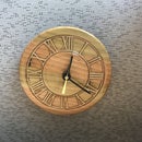
Introduction: PiAware Radar Kiosk


Earlier this year, I became aware of a very interesting company called FlightAware which offers flight tracking of both private and commercial aircraft throughout the world. As part of its service, Flight Aware relies a lot on crowdsourcing of its tracking data from thousands of private radio receiving stations that monitor the Automatic Dependent Surveillance – Broadcast (ADS-B) signals of any aircraft that are flying overhead.
These signals provide the GPS location, altitude, speed and direction of the aircraft, which can be easily received by a radio receiver and sent to FlightAware to provide real time tracking.
The beauty of this arrangement is that this information can be received and sent by a lowly Raspberry Pi and a very inexpensive SDR (Software Defined Radio) dongle. This type of receiving station is more commonly known as a PiAware station.
Having a spare Wi-Fi enabled Raspberry Pi on hand, I was pretty intrigued by this and after ordering a $20 SDR dongle off of eBay, I was up and monitoring the airplanes in my area.
One of the neat features of the PiAware system is that you are able to see a real time map of what your PiAware station is receiving via a web interface that you can view on a computer that is part of your WiFi network. As an added bonus, the PiAware web interface also gives a live weather radar picture for my area.
That's where there the inspiration for this project started. I also had a rather elderly Raspberry Pi 1 Model B kicking around. While the old girl was a bit slower than its newer siblings, it still had a lot of life left in it. As part of my investigation on what I could do with an old Pi - I stumbled upon some details on how you can use a Raspberry Pi as a web browser kiosk - similar to those that you see in places like airports to display up to date information.
And with that the SkyAware Radar Kiosk was born.
Step 1: What You Need to Build This


This is a fairly complex project in that there are a fair number of parts. However all the electronic components are pretty much plug and play for the most part.
Therefore, to build this kiosk, you need the following:
Electronic Parts
- Raspberry Pi 1 Model B
- Wi-Fi dongle for the Raspberry Pi (not required if your Pi has Wi-Fi built in)
- 7 inch LCD screen with Video driver board - I ordered mine off of eBay for about $30 - make sure that the board has a HDMI input
- A short HDMI cable - I ordered mine from eBay for a few dollars
- 12V to 5V converter board - again from eBay for a couple of dollars
- Short USB extension cable - also from eBay
- Short USB phone charger cable - eBay again
- Male and Female Power connectors - I got mine from my local surplus store
- 12V power laptop computer supply - Also from my local surplus store
- A few lengths of hook up wire.
Wood Parts
- Two 11.25" X 5.75" X 0.5" pieces of Birch for the case front and back
- Four 4.5" X 4.5" X 0.5" pieces of Birch for the case sides
- One 4.5" X 5.75" X 0.5" piece of Birch for the case top
- One 8" X 12" X 0.5" piece of Red Cedar for the case bottom
Tools and Supplies
- Table saw
- Mitre saw
- Router table with straight and round over bits
- Dremel Trio or other such small rotary tool with a straight bit
- Sander
- Soldering iron and solder
- Wood glue
- Electrical tape
- Corner clamps
- Drill or Drill press
- Hot glue gun and hot glue sticks
- Felt furniture protectors
Step 2: Programming the Raspberry Pi


A small disclaimer - The Pi pictured in this step is a Raspberry Pi 3 B+ (I didn't think to take a picture when I was doing this step with the Pi 1 B that I used)
Setting up a Raspberry Pi as a web kiosk is actually pretty straight forward. In the most simplistic terms, all you need to do is install Raspbian onto your Raspberry Pi.
Raspbian comes installed with it's own web browser called Chromium. Chromium has a plug in feature where it can display itself in what's called kiosk mode which is basically a mode where the browser is displayed in a full screen mode with the mouse pointer either hidden or disabled. When you set your Chromium homepage to the page you want to display in the kiosk mode, the Raspberry Pi can be made to start Chromium in kiosk mode each time it boots.
The problem I had with this however come with the version of Raspberry Pi that I was using. The most recent versions of Raspbian is more geared to the more current versions of the Raspberry Pi. With my old Model A Pi, while it still worked, it definitely was having troubles keep up with the newer operating system.
As a result, I needed to find an older version of Raspbian that still had the kiosk functionality that I wanted, but didn't tax my older Pi too much.
After some research, I found that the 2016-09-28 version of Raspbian-Jessie to be the version that would work the best. The image for this version of Raspbian can be found here.
I downloaded the Raspbian image and flashed to a SD card
Once the image was flashed, I put the SD card into my Raspberry Pi, plugged in a keyboard and mouse into the USB ports of the Pi, hooked it up to a monitor with a HDMI cable and powered it up.
When booting up, the Pi should start in the “Windows” User Interface, click on the menu, followed by the systems menu item and open the terminal window.
In the terminal window type: sudo raspi-config
When the configuration menu opens, do the following:
- Expand the filesystem (option 1)
- Change the User Password (option2)
- Change Boot Options to "Desktop Autologin" (option B4 under Boot Options)
- Change your regional settings (option 5)
- Set your Hostname (option A2 under Advanced Options)
- Make sure SSH is turned on (option A4 under Advanced Options)
- Change the Memory Split to 128 (or more) for video or intense graphic content (option A3 under Advanced Options)
After that, reboot the Pi
NOTE – At this point we would typically get and install updates for Raspbian – it’s vital that we don’t do that in this case since we do need to maintain this version of Raspbian which would be lost with an update..
Once the Pi reboots, open up the terminal again and type the following commands:
- sudo apt-get update (we just want to know what is new for the few things we really need)
After the update finishes we have to download and install 2 packages that are not part of this version of Raspbian:
- apt-get install unclutter
The unclutter tool lets you hide the mouse pointer on your display
After this install, you should still be in the /home/pi user directory
We next need to create a script in this directory Create the script like this:
nano start_chromium.sh
- # Run browser after boot to desktop
- /bin/sleep 3
- sudo -u pi chromium-browser --kiosk --incognito &
- # End of script
Please note that the ip address will be for the ip address for your Pi Aware Flight Aware Skyview site. The easiest way to get this is to look onto the FlightAware account assigned to your PiAware setup and clicking on the Flight Aware link - cut and paste the web address of the website that pops up with your Flight Aware map.
Ctrl-x to close and save the file.
The next step is to make the script executable.Execute following commands from the command line:
- sudo chmod 755 start_chromium.sh
- sudo chmod +x start_chromium.sh
Now that the script is executable, the next step is to modify the autostart file:
sudo nano /home/pi/.config/lxsession/LXDE-pi/autostart
- @xset s off
- @xset s noblank
- @xset -dpms
- @unclutter -idle 5 -root
- @/home/pi/start_chromium.sh
- You also need to comment out one line with a #, so edit to look like this:# @xscreensaver -no-splash
Now you can Crtl-x to close and save the file.
The first 3 xset commands work together to stop the screen from blanking after a few minutes. The unclutter command hides the mouse pointer on your display after 5 seconds. Then the new script we just built is executed.
We are done! At this point type:.
sudo reboot
And you should start seeing your Flight Aware map showing up on the screen once the pi has restarted
Step 3: Cutting Out the Front and Back


Now that the coding for the web kiosk is done, the next step is to build the cabinet that the Raspberry Pi and screen will live in.
It would actually be pretty easy to make a simple box to house all the electronics, but I wanted to make this cabinet to be a bit more unique, so I eventually decided on a hexagon shape for it. The nice thing about this shape is that while it is unique - it is still pretty easy to build.
To build the cabinet, I started by cutting out the front and back since the front and back can serve as a gluing jig when I go glue the sides of the case together later on.
To create the front, I first measured the size of the LCD display that I would be using and I cut out a template of the screen on a piece of cardboard.
With the cardboard template I then laid it out on top of one of the 11.25" X 5.75" pieces of birch. When laying the template on the wood, make sure that the wood is laid out in a diamond shape in relation to the screen template.
When the template is centered on the board, trace out the outline of the screen onto the wood with a pencil.
Next make a mark on the wood 2 inches off from each of the longer sides of the screen outline that you just marked.
With a miter saw, cut a straight line on the marks that you just made on the boards. Make sure that your cuts are parallel to the long sides of the screen template that you have drawn.
Once you've made the cuts, you should now have a hexagon shape with a long top and bottom with all corner angles cut at a 22.5 degree angle.
Using the case front that you have just cut out, trace the pattern over the other 11.25" X 5.75"piece of birch and cut out the back of the case using miter saw.
Step 4: Cutting Out the Screen Opening


Once the front and back of the cabinet have been cut out, we next need to cut out the opening for the screen on the front.
Using the template outline that we drew on the front in the last step, I used a small rotary tool (in this case my trusty Dremel Trio) and with a straight bit, cut out the screen opening by carefully and slowly following the line drawn on the wood.
Once the opening is cut out, we need to make a groove that follows the outside edge of the screen opening on the inside of the cabinet front. This groove is for allowing the non display portion of the screen to fit into the front snugly. To make the groove, I reset the rotary tool so that it only cut at a depth of a 1/4 inch and I then cut a half inch groove along the outside edge of the screen opening.
Step 5: Preparing the Side Pieces


The next step in the process is to prepare the sides of the cabinet. More specifically we need to add a 1/2 inch groove along each edge of the sides in order allow for the front and back of the cabinet to be seamlessly and snugly fitted into the sides when we go to assemble everything together.
To create the grooves, install a 1/2 inch straight bit into a router and set the router's cutting depth to 1/4 inch.
When the router is set up, take a couple of 1/2 inch birch boards and just run the two long edges of the boards through the router such that you will have a 1/2 inch wide and 1/4 inch deep groove along each long side of the boards. Make sure that the grooves are on the same side of the board.
Step 6: Building the Corners


Next we cut out the sides for the cabinet.
Start by cutting out four 4-3/8 inch long sections from the 1/2 inch birch piece that we put the grooves in during the last step.
When cutting out the first two pieces, cut them with the miter saw set at a 22.5 degrees and cut at this angle on both end of the boards. When cutting the boards, make sure to cut them such that the longer part of the angles are on the side of the board that does not have the groove cut into it.
When cutting out the last two pieces, cut one side with a 22.5 degree with the miter saw, then cut the other side at a 45 degree angle. Again, when cutting the boards, make sure to cut them such that the longer part of the angles are on the same side of the board that does not have the groove cut into it.
With the pieces cut out, glue the two sides together on the 22.5 degree corner for each board and clamp them with corner clamps. The pieces should have what would appear to be two greater than (<) signs.
Once the glue has dried, remove the clamps.
Step 7: Assembling the Cabinet


To assemble the shell of the cabinet we need to utilize the front and back of the cabinet as a template.
Start by putting the 2 corner sides of the case that we built in the last step together with the front and the back pieces, making sure to fit them into the grooves that are cut into corners.
Cut a 6 inch long length of 1/2 inch grooved birch with a miter saw set to cut at a 22.5 degree angle. Make sure that the "long" part of the angles are on the side of the birch board that does not have a groove cut into it.
With the board cut out, place a bit of wood glue along the 22 degree edges and attach the board to the top of the cabinet, making sure that the top is securely attached to the corner sides of the cabinet. Before attaching the top, I usually put a bit of masking tape on the top corners of the front and back pieces in order to avoid any unintentional gluing of the front and back while we are going the top to the sides.
As an added measure, I also secured the top to the sides with some masking tape until the glue has dried.
Step 8: Installing the Front Panel


With the basic shell of the cabinet assembled, the next step is to permanently attach the front panel to the cabinet body.
In this situation, it is a fairly straight forward manner of just running a bead of glue along the inside grooves of the case and firmly seating the front panel into the groove until the front is flush to the edge of the cabinet shell.
Step 9: Creating the Base


The base that the cabinet will be mounted on will be a made out of a 12 inch X 8 inch piece of 1/2 inch thick piece of red cedar.
In order to provide a bit of a contrast to the sharp angles of the cabinet, I decided to make the base in the form of a half circle.
To make the half circle, I used a large bowl as a template and I traced a half circle onto the red cedar board.
I then cut it out with a scroll saw.
As a way to clean up the edges of the circle I ran both sides of the board through a round over bit on the router.
Step 10: Installing the Base


Before installing the base to the cabinet, I first give both pieces an overall sanding.
Once everything is sanded, we want to install the cabinet such that it is in the middle of the base, with the back of the cabinet flush with the back of the base. Start by positioning the cabinet on top of the base, making sure that the cabinet is completely centered on the base. To make sure that things are completely centered, I used a ruler to measure in from the edge of the base to the edge of the cabinet, the distance needs to be the same on each side of the cabinet.
Once the cabinet is centered, mark the location of the on the base with a pencil
Remove the cabinet and apply a bead of glue along the bottom edge of the cabinet. Attach the cabinet to the base at the location you had marked and apply a little bit of clamping in order to ensure a tight bond.
Once the glue has dried, you can remove the clamps.
Step 11: Varnishng the Case

With the cabinet finally assembled, I gave it a couple of coats of spar varnish, with a light sanding of steel wool between coats.
Step 12: Adding the Screen


With the cabinet build complete, we now start installing the electronic components for the kiosk.
We start the installation with the LCD screen display. When I looked at the screen I first noticed that the screen had a galvanized metal border around the display. While that in itself is OK, I did notice that the border was quite noticeable when I did a test fit of the screen in the cabinet.
To mask the border I applied a strip of black electrical tape along the border of the screen.
Once the tape was applied I then installed the screen into the cabinet. I then secured the screen in place with a bead of hot glue along the screen edge.
Now, from this point forward I do want to recommend that you use extreme caution in handling the cabinet going forward now that the screen has been installed - I found that out the hard way!
Step 13: Installing the Display Board


With the screen installed, we next install the driver board for the screen.
Connect the ribbon cable that is attached to the screen to the display board.
Apply a little bit of hot glue to the back of the board and attach it to the back of the screen.
Once the glue has dried, plug in the HDMI cable into the HDMI port on the board and then plug in the cable for the control switch board into the display board.
Apply a bit of hot glue to the back of the screen and attach the control switch board to the screen.
Step 14: Preparing the Back


Before we get much further into the electronic install, I wanted to do some prep work on the back of the cabinet.
While for the most part the back is effectively a plain piece of wood, we still need to have some ventilation put in to allow the heat to dissipate from the electronics that are going to be housed inside the cabinet.
To create the ventilation holes, I first marked a series of evenly spaced drill points along the top of the back.
Once the back was been marked up, I drilled 3/8 inch holes at the marked locations with a drill press
Step 15: Installing the Raspberry Pi


Shifting back to the electronics installation, we next focus on installing the Raspberry Pi into the cabinet.
To provide as much ventilation for the Pi as possible, I chose to have the PI sitting in as much open air as possible. To accomplish this I decided to mount the Raspberry Pi on top of a small block of wood which in turn would be attached to the bottom of the cabinet.
So, with a bit of hot glue, I attached the small block of wood to the bottom of the cabinet, I then attached the Raspberry Pi on top of the block of wood.
Once the glue had dried, I plugged in the other end of the HDMI cable into the Pi and then plugged in a micro USB cable into the power port of the Raspberry Pi.
Step 16: Completing the Back of the Cabinet


Returning once again to the back of the cabinet, we need to cut out access for the USB cable for the Raspberry Pi and to provide access to a power connector for the kiosk.
Starting with the USB port, I traced the outline of the port onto the bottom right side of the back.
Next I traced an outline of the power connector onto the bottom left of the back.
After tracing the openings I then drilled a 3/8 inch hole in the middle of the traced openings. I then enlarged the holes to the proper size with a rotary tool and a straight bit.
Step 17: Preparing the Power Supply


With the main components now installed we now need to put in place the bits that we require to power up everything up.
For this project we have 2 different power requirements. The screen requires 12 volts of power while the Raspberry PI needs 5 volts to operate.
The best way to accomplish this is to have the main power for kiosk be derived from a 12 volt power supply with a step down convertor to provide the 5 volts for the Pi.
In order for all of this to come together we need to construct a wiring harness for the power supply. To build the wiring harness we first need to determine the polarity of the power coming out of the power supply. To do this, I connected the female power connector socket to the laptop power supply and hooked up a multimeter to the leads on the power connector. I noted which lead was negative and soldered a length of black wire to that lead.
For the other lead (which would obviously be the positive lead) I soldered a length of red wire. On the other end of the wires I connected a male power connector, which will be plugged into the screen drive board.
Next I took a 12 to 5 volt step down converter and wired a length of red and black wire to the positive and negative terminals of the converter. I then soldered the other ends of the wires to the their respective leads on the power connector.
With that the wiring harness for the power was complete.
Step 18: Buttoning Things Up


We are now on the final stretch.
Plug the male power plug into screen driver board and plug the other end of the USB cable that is plugged into the Raspberry Pi into the 12 volt to 5 volt converter board.
Apply a dab of hot glue in a location on the inside of the cabinet and attach the 5 volt converter.
Install the female power connecter into the back of the cabinet in the opening we cut for it and hold it in place with some hot glue.
Next install the USB extension plug into it's location in the cabinet back and also hold it in place with some hot glue.
Plug the other end of the USB extension cable into an output USB port on Pi and finally install the back of the cabinet into the cabinet itself by gently pushing the back in (it should be able to be held in place by friction).
Step 19: Finishing Touches


Finish off by attaching some felts on the bottom of the cabinet, plug in the power supply and the kiosk should start right up!
This kiosk has become a very essential eye in the sky for me. Not only does it allow me to monitor the activity of my PiAware set up, it gives one a very educational view of the air traffic in my area and I can actually identify the air routes in my area.
As added bonus, I also now have a live weather radar screen - an important tool during thunderstorm season!
Thanks for checking out my Instructable - if you find this intriguing, please check out my site to see what other things I'm tinkering with!

Participated in the
Epilog X Contest

![Tim's Mechanical Spider Leg [LU9685-20CU]](https://content.instructables.com/FFB/5R4I/LVKZ6G6R/FFB5R4ILVKZ6G6R.png?auto=webp&crop=1.2%3A1&frame=1&width=306)


