

Introduction: PiDP-8: a Raspberry Pi As PDP-8 Minicomputer


Everyone wanted a PDP-8 minicomputer. Well, in 1968 anyway. Relive the Golden Age of minicomputers by booting this SD card image on a Raspberry Pi. Optionally, add a replica front panel to recreate the Blinkenlights experience. A simple Hacker's Version can be made for less than $35 in parts. See my PiDP-8 web site for full details.
Why? Why not? To illustrate how utterly unique the PDP-8 was in the evolution of computing. Control the world, play the very first video game, or hook up 8 terminal sessions to let it run your company. It's a minicomputer... The PDP-8 is also an incredibly good way to learn about how a computer works at the lowest level. Because it is a very simple machine, yet has loads of good software.
How? There's 3 stages to this project:
- Software-Only: boot the SD card image on your Pi (A+/B+/2/Zero). The Pi will boot up as a PDP-8.
. - Low-cost hardware hack: add the custom front panel PCB and you have a fully functional hardware replica.
Board can be made from the Gerbers by OSHpark, Seeedstudio, Elecrow or anyone else. Or buy it from me ($15, leave a message here). Total cost depends on your parts shopping, but could be well below $35...
Fancy replica kit version: I made this into a kit, with pretty acrylic front panel, custom switches and bamboo case. See here (link) for details on when the next batch of parts is made.
This Instructable covers stages 1 and 2, as a hack-it-yourself project. Not stage 3; if you prefer to buy the replica kit, see here.
Step 1: Software: Booting a Pi As a PDP-8

The pidp8 software boots an emulated PDP-8 on your Pi. Although intended to drive a replica front panel, it runs fine without the actual hardware. This page here describes some of the things you can do with a PDP-8.
Two software options:
- download the ready-made SD card image, it boots up the PDP-8 in less than 10 seconds.
Works on Pi A+/B+/2/Zero. Not yet on the Pi 3. User: pdp. Password: pdp. - or install the tarball on any standard Raspberry Pi distribution. This gives you a standard Raspberry Pi environment that allows you to do whatever else you'd like to do with the Pi-inside-the-PiDP. Works on the Pi 3 as well.
See this PiDP forum post for details. Whether you chose Option 1 or 2, the PDP-8 terminal should come up straight after you log in, with OS/8 running. Even though the physical front panel is not attached yet. You can escape out of the PDP-8 (it will keep running though) into Linux with Ctrl-A d, and return to the PDP with ~/pdp.sh
Without the physical front panel, you will need to mount the different boot configurations on the keyboard rather than through the front panel:
- Hit CTRL-E to get to the simulator command line,
- enter do ../bootscripts/x.script . Where x is a number from 0-7, to boot into TSS/8, the spacewar video game, or whatever tickles your fancy. With the hardware, you'd do this on the front panel...
By the way, a very nice way to look at a PDP-8 screen is to use a CRT emulator.
Step 2: Circuit Board: Adding Blinkenlights

The PDP-8/I was reputed to have the best Blinkenlights of all minicomputers. Its front panel did not show just a memory address and its contents, but a lot more. Such as which of its 8 CPU instructions is being executed. Of course, the front panel also allows you to enter and examine programs. But more often, you use it to single-step through a program or load a new one.
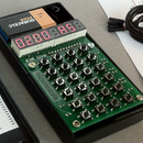
The PiDP circuit board is a faithful, scale 2:3 replica of the original. Meaning it has 89 LEDs and 26 switches to work with. The Raspberry Pi is plugged in to the back of the PiDP board and that's it: you don't need much these days to make a minicomputer.
Getting the circuit board: The Kicad design project can be downloaded here. To produce your own, send these Gerber files to someone like Seeedstudio or OSHPark. Or, you can contact me if you want to buy one from me for $15 (not-for-profit hobby BTW).
Note - this Instructable describes how to 'roll your own' PDP-8. It is not a building guide for the PiDP-8 replica kit, which comes with its own replica switches, acrylic front panel and case.
Step 3: Soldering the 89 LEDs
First thing is to mount the LEDs. Polarity matters. The long legs must be on the left, closest to the Raspberry Pi. Just to leave no doubt: The short legs should be facing the end of the PCB which has the PiDP logo on it.
The video shows an efficient soldering technique: with one hand, soldering iron already wetted with a blob of solder, fix up one pin of each led, whilst holding the PCB with your other hand, pushing hard against the LED with a finger. That's not a generally good soldering technique, but in this case it will help getting the LEDs into straight rows.
At the end, check whether the LEDs all sit straight (if not, reheat pin and reseat), with polarity correct, then solder up their second pins.
Step 4: Add Resistors and Diodes
Continue by fitting the 26 diodes above the switches, on the front side of the PCB. Then proceed with the three 1K resistors close to the row of diodes, also on front of panel, then the block of twelve 390 ohm resistors, on the back of panel.
For diodes, polarity matters: check that the black strip on the diode matches the stripe on its PCB footprint.
Step 5: Fit IC Socket and Raspberry Pi Connector
Solder the 2981 IC on the back side of the board (check!) and make sure it sits with pin 1 facing down to the switches on the other side of the board. Lastly, solder in the 40-pin header that will connect to the Pi. Do not solder it into the footprint of the Expansion Connector, a mistake that's easily made. Solder 1 or 2 pins first, then check the connector sits exactly perpendicular to the PCB. Correct if needed, then solder up all the pins.
Things to ignore: The X and X*2 ohm resistors marked on the PCB must be left out (they're not included in the kit anyway) unless you enable the serial port (see last section on this page). Also, the jumper blocks J_COL1 and 2 can be left untouched. Lastly, there's two solder points close to the 2981 IC. Ignore them too.
Step 6: Add Switches

The circuit board can take pretty much any small switch, the only important thing being that their width is less than 10mm. The original had momentary switches on position 20-24. But you can use toggle switches for them as well, the software will convert their signal into a momentary one anyway.
Only two pins are soldered on the board (for on/off signals). If your switches have a 3rd pin, just leave it hanging below the edge of the PCB. Depending on the switch you use, you may have to bend its pins about 0.5mm to fit. The solder holes are large enough to take pretty much any type of solder lug.
The photo shows some suggestions for possible switches. Look for MTS-102, or (especially nice) RLS-102-C1 & RLS-112-C1. Basically, anything that makes a short between the two solder holes on the circuit board will do though.
Step 7: Wrapping Up


You can mount the front panel on a wooden base panel using standard shelf brackets, their screw holes should align with the mount holes on the PCB as the spacing follows an apparent norm... Mounting the board this way should allow for some very robust toggling action.
An effective way to create a proper frontcover for the Blinkenlights is to print out this image. Either as a decal to stick on an acrylic sheet, or simply on paper. In which case you could laminate it, or place it behind an acrylic panel.
That's about it! Total cost should be around $15 for the PCB, plus the cost of a bag of LEDs etc, and 26 small switches. Visit the PiDP web site for details on how to operate your minicomputer hack - and how to debug it if things do not work at first :)


