

Introduction: Portable Raspberry Pi Emulation Station With Retro Pie


In this Instructable I'm going to show you how to take a small Pelican case and and Raspberry 1 B+ and turn it into a completely portable gaming system.
I'm going to give you a working parts list, take you step by step on how to design and build your very own completely portable gaming system, and then at the end link some videos I've made that explain how to build it and load your software onto it, and hopefully make this build an easier and less daunting undertaking that it can sometimes seem to be.
So sit back and relax as I instruct you on how to make your own gaming system that will be the envy of family, friends, and the occasional passerby.
Step 1: Parts Required*

So this is a very simple and easy build to make that requires little skill to pull it off. The only tools you will need are a dremel for cutting a square large enough for the screen and ports for air vent and USB/LAN access, a drill with metric bits and a hole cutter, a small socket set/screwdriver, soldering iron/solder, and a ruler (prefferably metric for the most accurate measurement).
With this build it will take several parts but is fairly easy for a beginner to piece together:
1 - Raspberry Pi 1 B+. The three won't work with this build as it requires too much of an amperage draw that you just can't get with the battery that I've listed. If a battery bank can be found with an output of at least 5v 1amp on one charging port and 5v 3amp on the second, then the Raspberry Pi 3 B+ should work. I will update this instructable with the make/model if I'm ever able to find one myself.
https://www.amazon.com/Raspberry-Pi-Model-512MB-Co...
1 - 5v 30x30x7mm fan to cool the Raspberry Pi. Look on Amazon for Pi specific fans as those will usually come with heat syncs as well which you will need to maintain a safe operating tempurature within the case.
https://www.amazon.com/Gdstime-Aluminum-Heatsink-R...
1 - 7 inch TFT screen. You don't have to use the one linked below, this is the closest to the one I used.
https://www.amazon.com/Makerfire-7-Inch-Raspberry-...
1 - SNES Controller for PC (these ones have a usb connection and are roughly $8 on Amazon)
https://www.amazon.com/Gtron-Retro-USB-Super-Class...
1 - Pelican 1120 case. I've linked the black case, but you can find them in a few other colors as well.
https://www.amazon.com/Pelican-1120-Case-Camera-Bl...
1 - 20,000 mAh portable batter pack. A smaller battery does work, my spare is a 10,000 mAh battery pack that provides on average 6-8 hours play time depending on if you're overclocking the Pi and at which setting is being used. The one linked is what I used, but as long as you stick with a battery bank with those dimensions or smaller it should fit in your build.
https://www.amazon.com/Vinsic%C2%AE-20000mAh-Porta...
1 - Micro usb cable for the Pi's power supply. Something under 1 foot long is best used.
https://www.amazon.com/Anker-PowerLine-Premium-Mot...
1 - 5.5 x 2.1mm male power adapter. This is the only part of the build that requires soldering
https://www.amazon.com/Electop-5-5mm-Power-Pigtail...
1 - old usb charger cable, this will need cut to make the power adapter for the screen so make sure it's one you no longer need. Also, before you start hiding the wires, make sure to test that the cable will provide power to the screen.
1 - 270 degree HDMI adapter. Ensure it is a 270 degree and not a 90 degree as the 90 will get in the way of the power supply.
https://www.amazon.com/Cable-Matters-Degree-Vertic...
1 - 1.5 foot HDMI super thin/ultra thin cable
https://www.amazon.com/BuyCheapCables%C2%AE-1-5ft-...
1 - Aux/3.5mm through panel/panel mount adapter.
https://www.amazon.com/3-5mm-Stereo-Feed-Thru-Pane...
1 - 6" Aux cable
https://www.amazon.com/kenable-3-5mm-Audio-Stereo-...
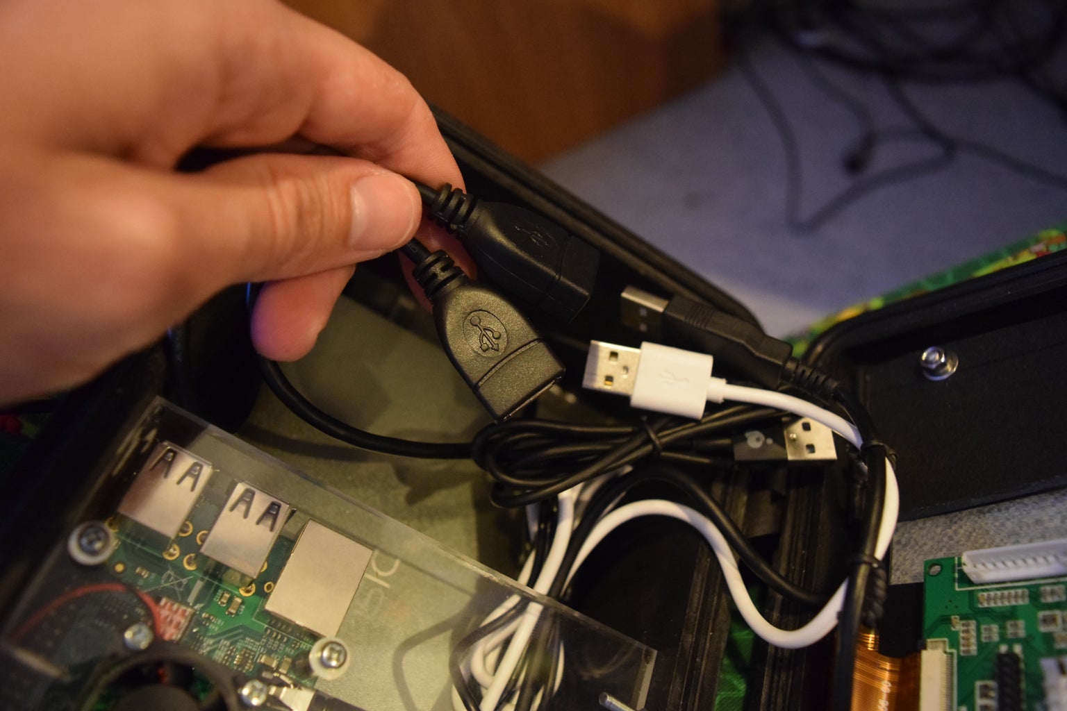
2 - Left/Right USB extension cable. The type of cable required will depend on the type of battery you use. For instance, in my build I had to make use of both a left and right angled cable because of the USB connection layout on the battery pack.
https://www.amazon.com/UCEC-SHORT-SuperSpeed-Exten...
1 - 3mm piece of plexiglass to mount the Raspberry Pi to. You can use any material here as long as it is rigid and easily cut. I would not recommend metal because of the heat that the Pi puts off. Plexiglass was easy for me since with the right cutting tools you can either score it and break it along that line or use a dremel to cut.
https://www.amazon.com/Dazzling-Displays-Clear-0-1...
1 - Roll of double sided tape. This will be used to adhere the screen onto the pelican case and to also adhere the battery bank to keep it from bouncing around as well.
https://www.amazon.com/Rextin-Meters-Adhesive-stro...
1 - Piece of rubber to mount the screen control board to the back of the screen and prevent a short in the circuit.
https://www.amazon.com/6x6-Inch-Neoprene-Plumbing-...
4 - PCB board standoffs, I used 20mm standoffs and they left just enough space for everything.
https://www.amazon.com/EMY-Stand-off-Accessories-A...
1 - Small box of M3 nuts and bolts at least 20mm in length, these will also come in handy when mounting the Raspberry Pi to the plexiglass as the bolts provided with the PCB bard standoffs aren't long enough to reach through the plexiglass. Note that you may need shorter than 20mm bolts, but usually you can find 10mm in packs of 4 so you're not buying more than necessary.
Step 2: Installing the Screen


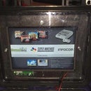
So to install the screen you first need to measure out the part of the screen that will actually display the operating system. Usually there is a few millimeters along the edge that does not display anthing, you will use that small space to put double sided tape to and adhere to the pelican case.
Double check, no, tripple check your measurements to ensure you do not cut too large of a hole for the screen in the lid of the pelican case. If you cut too big then your screen will be much more difficult to install. When I got my measurements and I traced out the area to cut I made sure to cut the hole too small and then used my dremel to shave away little by little and checking against the screen to ensure I did not cut too much off. This is the one part that is a bit time consuming but well worth it, this is what everyone will see and if you are able to make clean even cuts and adjustments your project will look all the better for it. Also, that big rectangle you just cut out? Don't toss it, it is going to be useful for this project...
Now in the second picture you can see the back of the screen and...wait what is that?...It's the scrap rectangle I cut!!! Yes, this is what that scrap will be used for so make sure you try to cut it in one big piece instead of multiple smaller pieces. So what I used it for was to help hold the screen against the pelican case and the double sided adhesive tape to make a firm hold so the screen doesn't fall out.
BE CAREFUL when you bolt down the scrap plastic to hold the screen in place. I cracked my touchscreen on mine doing this and had to use a heat gun to remove it and disable it's touchscreen capabilities. To get around this I used washers so that the plastic was just barely above the back of the screen and then used the thin double sided tape to make up the difference and create a better hold
When you get ready to drill the holes to hold the screen down ensure you run the HDMI and power cable around (I did mine on opposite sides of the screen as it was easier) so you can ensure you leave enough space between the bolts and the screen so you can hide these cables under the scrap plastic so as to tuck them out of the way.
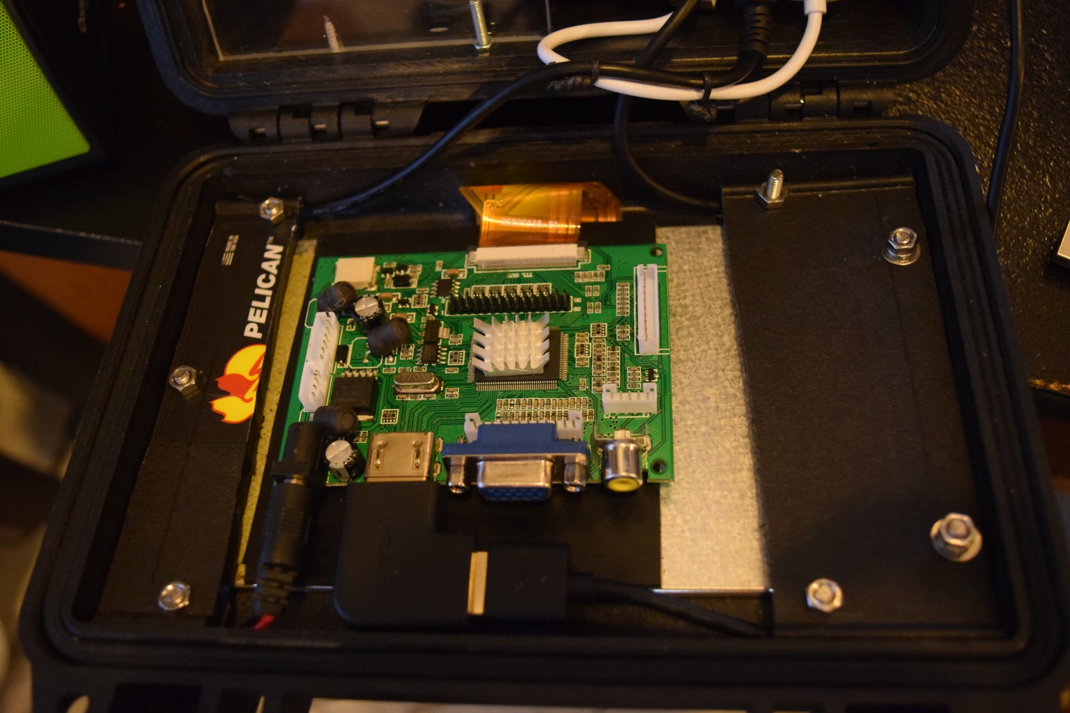
The final step for the screen is to mount the screen control board and the cables. This is where that piece of rubber with a sticky side comes into play. As stated in the parts list, this piece of rubber is to ensure that no shorts happen between the control board and the screen resulting in frying the board and or screen. To adhere the board to the screen I just layered the double sided tap until I got a nice flat surface and then mounted it to the rubber piece attached to the screen. Make sure to mount it low enough to allow enough space for the cables to plug in without being wedged too tightly against the case lid. To ensure proper clearance I suggest plugging the HDMI 270 degree adapter and the power cable in, but not to the power source, and then attach it to the screen. I didn't do this and had to re-adjust it several times.
Once you finish this part, the rest is much much easier.
Step 3: Screen Power Adapter


Now for this step it does require a little electrical know how. If you don't have that then just watch the linked video where I fully explain how to wire a custom adapter using that 5.5 x 2.1mm adapter and the old USB charger cable you snagged earlier.
The quick footnotes for this step are to ensure you run enough cable for the adapter to reach the screen and the battery. Now when you cut the USB cable to get to the wires you will find 4 wires inside, 2 are for power and 2 are for data. You need to separat the red and black wires and cut the other two down. The red wire is the positive wire and the black wire is the negative wire. Solder these two wires to your adapter accordingly and it will power the screen just fine. Below is the video I HIGHLY recommend you watch before doing this step as I go into extended detail as to how to achieve this and you can see the type of adapters I used.
Step 4: The Power Supply


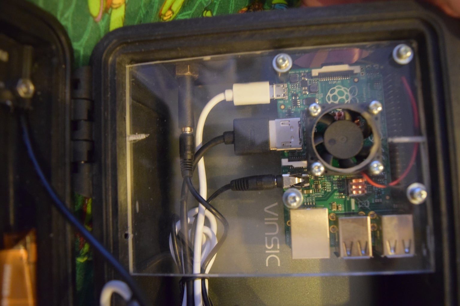
The power supply as you can see is a thin 20,000 mAh Vinsic Battery Bank that would normally be used to charge cell phones or tablets while you travel. Because your project only requires very little in the terms of sustained power these work great for this type of project. And like I said in the parts list you don't necessarily need a bank this large but I prefer it as it ensures my system will last for almost an entire day, this bank here gets me just shy of 14 straight hours of game time.
The only special step here is to make sure the power supply you buy will fit in the bottom of the pelican case with your USB right/left angled adapters and preferably the charging cable as well. As you can see in the middle picture, I used double sided tape on the battery to make sure it doesn't bounce around within the case. Second thing you need to note is that the port you plug the Pi into is the one with the highest amperage output. Raspberry Pi's generally require about a 2 amp supply where as the screen only requires about 500 mA supply. As you can see in the third picture I have a white and a black usb plug, the white connects to the Pi where as the black connects to the screen. Though you can't see it in the photos, I did mark on of the usb extension cables so I knew which had the higher amperage supply. The Raspberry Pi will still run if it's under powered, however you will notice a multi-colored block in the upper right hand corner of your screen along side a very sluggish gaming experience.
I will also reitterate what I stated in the parts list; this battery doesn't supply enough amperage for the Raspberry Pi 3 B+. I am looking to see if one comes out eventually that will provide the required 5v 3amp output and test it on my other build that uses the Pi 3, but until then I have to remind you that this project is just for the Raspberry Pi gen 1 boards. Gen 2 may work, but you need to compare the power requirements between the generations to ensure you're not underpowering your system.
Step 5: Mounting the Raspberry Pi


Now you're finally almost done with your project! If you've made it this far without rage quiting congratulations! this part is easy-ish.
Ok so first thing is first, you need to cut your mounting plate (mine is plexiglass) to fit inside of the pelican case. I used 5mm for mine but I would recommend 3mm as it's cheaper to buy, easier to cut, and doesn't retain heat as much as some other materials like metals. If you look inside your case you will notice that there are verticle ridges inside the case, if you can, I would recommend cutting the plate to rest on top of these as it makes holding it in place much much easier and will ensure plenty of clearance for the back of the screen and screen board. I used bolts that come just overtop of the plexiglass to hold it down but I'd suggest using an L bracket as it will look much nicer. But since it'll be inside the box whatever is easier for you is the best bet. And as long as you do your measurements right its really easy. I cut mine to be about half of the width of the box to allow airflow with the fan mounted above. If you cut it about 1mm large and then just shave the plate down and testing the fit, it makes this process very easy. Also as a side not, if you use a grinding wheel on your dremel like I did wear long a long sleave shirt and gloves as the plexiglass thends to melt and it's very hot and will burn you. Not might, but will.
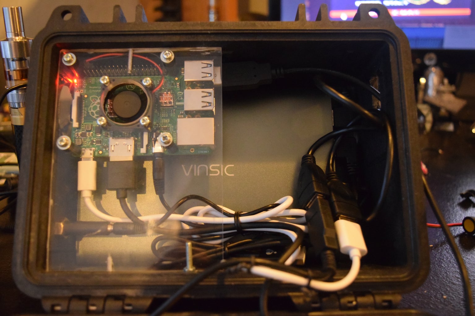
When you mount the fan I recommend mounting it to blow down onto the Raspberry Pi board so that you can also move the heat off of the screen control board. I also cut a hole in my case for a secondary fan but it required too much power so I abandoned it but it did allow the hot air to blow out. I wouldn't cut your hole as large as mine (picture 3) but I do recommend some slits to allow the hot air to be blown out.
Last step is to drill out a hole to mount the AUX adapter to the box. This will allow for you to use a small external speaker or headphones for sound. After you've finished this final cut, install the panel with the Raspberry Pi attached and hook up the aux cable, HDMI cable, and power cable to the PI. Once everything is bolted down you are basically ready to start playing your new system.
Now with my build you can see that the USB and CAT connections are on the inside of the box. This is the one area I wish I had done differently. I recommend having those against the case on the opposite side from where mine are and cutting a hole to allow easy access to those ports so you don't have to run cables inside of the box. I don't mind it so much since I have to open the case to connect power to everything regardless. As you can see in picture 4, I cut a small window in the side of the box to allow all controllers and the CAT5 cable to be run inside the box.
Step 6: FINAL STEP!!!

This step is by no means necessary but it is a good touch to add.
If you look on the side of the case where the lid is hinged you'll notice some rather large ridges that run up and down it. Cut those off. This gives your newly built gaming system a slight angle as it will rest on the hing and the now flat surface of the pelican case which allows for a much better play experience.
Step 7: Final, Final Step

So the last step to this project is to download Retro Pie onto an SD card and load it onto your Raspberry Pi Portable Gaming System and then upload your games.
Now a step I did not add was to install an audio system, since I generally use headphones or an external speaker with mine I didn't think it was necessary to add but there are tutorials out there that explain how to do this.
I hope this tutorial was very helpful to allow you to build a fairly inexspensive and fully portable gaming system. These builds are fairly easy to make and even more fun to game on. And being able to show it off to your friends is just awesome as you'll have your own one of a kind gaming system. If there are any questions about how to build this portable system please message me and I will be more than happy to help you out with your DIY gaming system. Below I will link the videos for how I built it and how I installed the operating system. The second video also has helpful links that explain how to install the system as well as the link for the operating system I'm using.
And if you're wondering what Dragon Ball Z game I'm playing, it's called Dragon Ball Z Team training. If you look up the game title on Facebook or google their website will pop up with links to download the game.
Video for installing the operating system:
Complete build video:
*Sidenote* in this video I did not use the 270 degree HDMI cable adapter but intstead cut the shielding from the cable, I do not recommend doing that as I ruined 2 spare cables before I bought the angled adapter. Also, using the jig saw was not a good idea, use your dremel for a better cut. And I've also swapped the battery in the video with the one in the pictures and used the shorter HDMI cable.

Participated in the
Circuits Contest 2016


