

Introduction: Programming Chips With Your Arduino - AVR ISP Covering ATTiny85, ATTiny2313 and ATMega328


I found this as a draft from many years ago. It's still useful for me at least so I'm going to publish it!
This Instructable is a pooling of knowledge collected from around the 'net and also the 'nstructables. It covers the programming of AVR Microcontrollers, using the examples of the ATTiny85, ATTiny2313 and ATMega328, with an Arduino. I've used this technique to build a range of gizmos over the years and have more recently used it to reclaim Arduinos that have been lost into projects, replacing them with a "bootloaded" ATMega328 and a handful of components.
This Instructable, like many, is built on the shoulders of giants. There are a great many sources and I hope to include them all, some of the biggest contributors are:
Arduino to Breadboard
High Low Tech Blog
Lady Ada's AVR Dude Tutorial
Randal Bohn's Arduino Sketch
If you want to really learn about the process it's worth checking out all the sources listed as they contain useful tricks and tips for when things stop working.
Ok so are we ready? Let's gather our tools. Following that we'll look at the code which does all the hardwork then at a few examples with the Arduino IDE, and we'll even take a short trip to the dark side with AVRDude!
Step 1: Gather Your Tools!
This is a fairly simple set up. I've never found capacitors to be an issue when using an official Arduino uno as a base so this might look a little bare to some who are experienced with AVR programming. You're going to need:
- An Arduino Uno
- Breadboard
- Jumper Cables
- Three LEDs and Three Resistors for 5V
and your choice of AVR Chip
- ATTiny85
- ATTiny2313
- ATMega328
You don't actually need the LEDs, but they are really handy to know that your programmer is working or if you have an error. Regarding the AVR Chip, you can program most AVRs with this method as long as you know where the RST, MISO, MOSI and SCK are located. The exception (that springs to mind) is that of the ATTiny10 and the like, they use a different method.
Step 2: Set Up Your Programmer
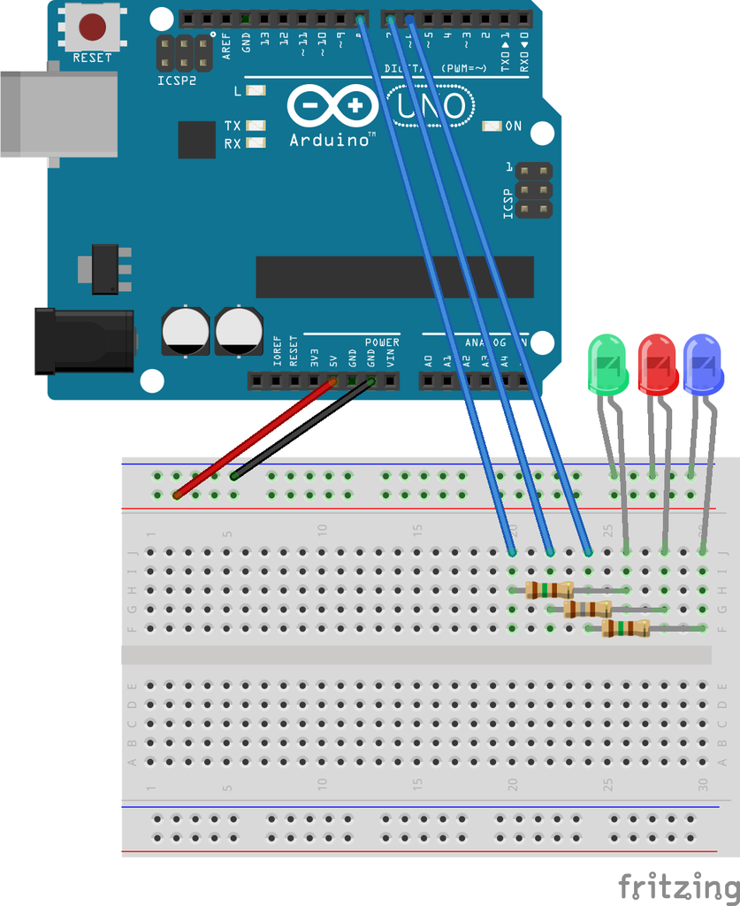
Lets set up the hardware first. We're going to connect up the LEDs so we can see when the board springs to life. Check out the diagram below. Put the shorter leg of the LEDs into the -ve or ground line on the breadboard, that's the one with the black wire going into it. Apologies if any of the things I'm saying appear patronising in any way, but I really remember what it's like to get started in electronics, so much was assumed knowledge and small things really held me up for some time!
If you haven't already, download the latest version of the Arduino IDE from the handsome folks at Arduino. If you're not using an official Arduino you might come across a few hitches in this method or you might not - you may also want to send them some beer money as they really do rock and as a community we owe a lot to them!
So do you have the IDE? (that's the software you just downloaded - IDE stands for Integrated Development Environment btw) Install that and plug in your Arduino, you can use the drivers that come with the IDE if your computer doesn't pick up the Uno right away. Now fire up the IDE.
The Arduino IDE does come with an AVRISP sketch all ready in the >Examples but it is really old. Head over to Github via this link click on the screen with all the text, hold Control press A to select all. Now hold control and press C to copy the whole text. Navigate back to your Arduino IDE and Control V to paste it.
Make sure the correct COM Port is selected (if you don't know which is the correct one you can right click on computer in the windows start menu (sorry not supporting other OS at this time!) then click device manager and left click to expand the Ports (COM & LPT) menu and it should show your Arduino as COM whatever). Now upload the sketch. All being well and all of your LEDs should flicker in sequence then one (I chose blue) will start to pulse. Try not to get hypnotised. Didn't work? Comment below and we'll see how we can help you through!
Once you have it working, save the sketch to your sketch book, using save as. You'll want to keep this handy for future reference.
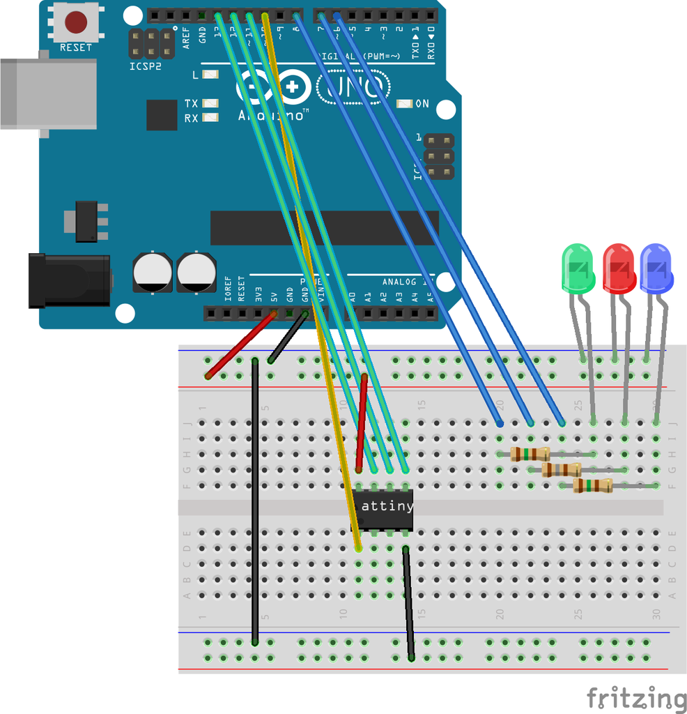
Step 3: Bootloading an ATMega328 - Making an Arduino Clone!
Now I'm starting with the ATMega328 as it's the easiest of the lot to do "out of the box" and there's an instant application. Burning a bootloader to make your own breadboard Arduino or Shrimp.
Check out the image below. Don't worry that it now looks exponentially more complex than the last step - it's just your brain tricking you, calm down and look at it again. The blue wires to the LEDs are the same, you've done those so lets not worry about them. The Black and Red wires from the Arduino likewise, they're your power wires, we want to get power to the chip. So add those. Now it's just 4 wires left. These are going to connect to your Pins 10 through 13 and for the curious these are:
- Digital 10 - RST (Reset)
- Digital 11 - MOSI (Master Out - Slave In)
- Digital 12 - MISO (Master In - Slave Out)
- Digital 13 - SCK (Serial ClocK)
So what we're actually doing is programming the chip by SPI Serial Peripheral Interface. Which is covered in this great tutorial by the mighty Sparkfun.
Now for the reason we looked a this one first. Go to >Tools on your IDE, Now >Programmer>Arduino as ISP. With that checked we can then go back to >Tools>Burn Bootloader. Now we're going to see some flashing LEDs and wait a while. The message at the bottom of your IDE should eventually turn to Bootloading complete. Hey presto, that chip on the breadboard can now be turned into a barebones Arduino!


