

Introduction: R/C Car Drag Racing Lights


This is an Instructable on how to assemble the "Drag Race Light Tree Kit" from Nerdykits and make an enclosure for the Race Lights.
PCB kit on ebay.com
Here are the files for the enclosure, they are in DXF files. The company I used to laser cut the enclosure is called pololu.com Note: Pololu.com was the only company that accepted the DXF files for laser cutting.
Material you'll need to assemble this kit:
- 1/8" (3mm) shrink tubing
- 9v Battery
- 22AWG wire. Different colors
- Solder wire
- 5mm LED bezel (holder)
- 2 small 1/4" long wood screws
- 2 10-40 bolt wit nuts
- PCB standoffs 1/2" or smaller.

Step 1: Enclosure and LED's


The enclosure is very simple. The bottom piece of the enclosure is from Michael's arts and crafts.
Open the PCB kit and remove all the hardware from the package. LED's, toggle switch, reset switch, buzzer and 9v Battery holder.
Start by soldering a 6" 22 AWG wires on the LEDs, make sure to label each lead for easy installation onto the PCB. see picture 4 and 5. Use 1/8" (3mm) shrink tube, to keep the LED's terminals from touching. pix 6.
Now solder 6" wires to the toggle switch, buzzer and reset switch. see picture 7.
Install the hardware to the enclosure. Toggle switch, reset switch and buzzer ( run the wires through the small opening firs then screw the buzzer down with 10-40 bolt and nut. install the battery holder to the upper right corner. see pix. 8, 9 and 10.
ON/OFF toggle switch on the left side, Buzzer in the middle and reset switch on the right side.
Step 2: PCB


solder all components onto the board. Do not insert the IC's.
Solder the LED's, make sure they get soldered in the correct place. see pix 3.
Now wire the switch, reset switch, buzzer and battery holder and install them onto the PCB.
The negative (black) lead from the battery holder to the negative post on the PCB.
The positive (red) lead from the battery holder to one of the terminals of the toggle switch.
From the other terminal of the toggle switch to the positive side of the PCB.
Solder the leads of the reset switch and the buzzer to the PCB. see picture 4, 5 and 6.
Insert all LED's through the enclosure. see picture 7 and 8.
Step 3: Assambly


Insert the LED's through the opening of the board, then install the LED bezel. Now push the LED back into place. see picture 1 through 9. I installed the red lights on the bottom, three yellows lights and green lights on top. you can change them as you like.
Now glue front (LED's) side and both side of the column together, then glue the column onto the top piece of the enclosure. see picture 10.
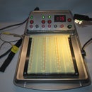
Before closing the enclosure, install both IC's and test your PCB for proper function and light sequence. Adjust the potentiometer to the light sequence speed that you like.
When you press the reset switch, it takes at about 3min for the lights to start over again. or just flip the switch off and back on if you don't want to wait.
Now at last glue the back side of the light column, and screw down the enclosure top. See picture 11.
Now that your done, call some friends and challenge them to a RC drag race. Have fun.


