

Introduction: RFID Door Unlock


A few times I have locked myself out of the house and needed to wait for the Wife to get home and unlock the door. So I decided to come up with a way to get inside the house if I am outside and have nothing on me. Using RFID tags hidden around outside I can put them to the reader on the door and have the door unlock. If I have my phone on me I can also unlock the door via an app I created.
The way the code works is we have 3 different RFID tag UID's in the Arduino program that will only unlock the door if scanned in the correct order. We can also use our phone and unlock or lock the door when on the same WiFi network as the Arduino MKR1000 using the WIndows 10 app that I created.
Step 1: Needed Items
Lockitron - Appears to be discontinued at most places. May take some searching to find.
RFID reader (generic)I used a RFID-RC522 from ebay
Adafruit TB6612 1.2A DC/Stepper Motor Driver Breakout Board
For the software portions I used the Arduino IDE and Microsoft Visual Studio 2015.
The code and stls for this project can be found on my github at https://github.com/keebie81/DoorControl
Step 2: 3D Printing
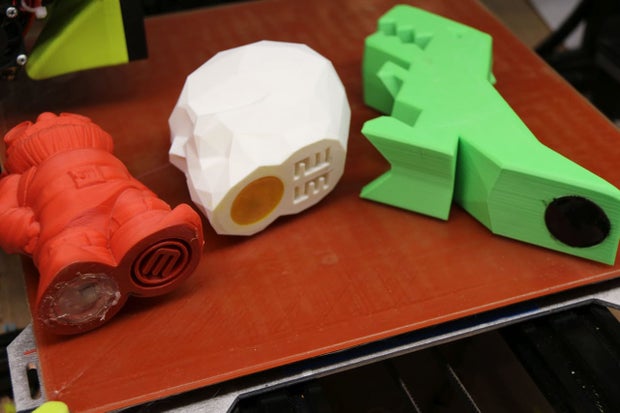
I 3D printed three designs to epoxy the RFID tags to. This way I can set them in the flower garden outside my house.
I printed a Makerbot Gnome, a Low Poly Skull, and a Robber Rex, all from Thingiverse.
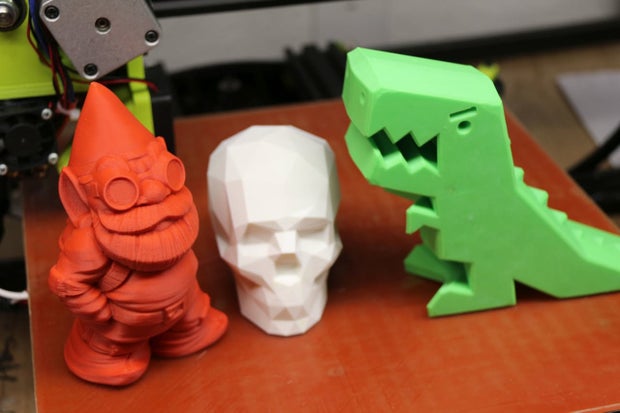
For the Makerbot Gnome I tried using hot glue for the tag but it did not flow well. For the Low Poly Skull and Robber Rex I used epoxy mixed with toner from used laser printer cartridges. This flowed a lot better and left a nice finish.
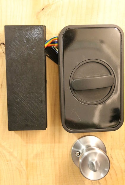
I also printed out enclosures to hold the components. I wanted to make something that didn't require any permanent modifications to the door. I came up with a design in Autodesk Fusion 360 that went in between the door and each side of the lock. This also allowed me to conceal the wires.
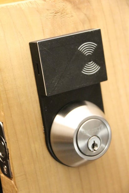
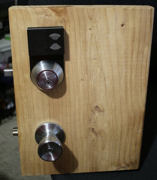
Front of door, RFID unit Concealed
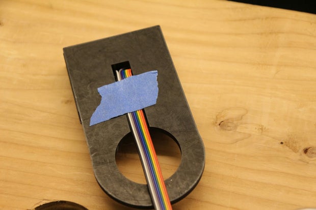
Wires concealed in channel
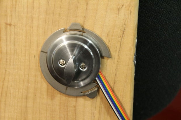
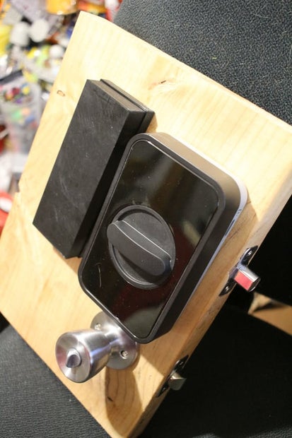
Wires coming from RFID module
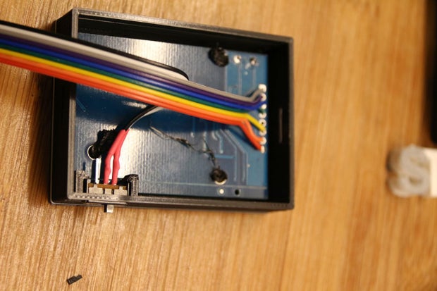
RFID module wiring and ON/OFF switch
For the indoor side of door I also made an enclosure to hold the Arduino MKR1000, Adafruit Metro Mini, Adafruit Powerboost 1000c. It attaches to the door in same way as front door part did.
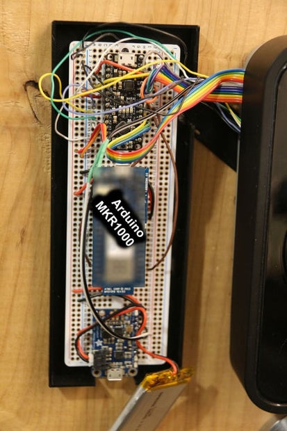
Circuit layout
Covered
Step 3: Door for Testing
Once I had all my parts printed out I made a fake door from some lumber. This allowed me to work out the bugs in my workshop and not mess up the actual door to my house.
Fake door outside
Fake door inside
Step 4: Wiring
We will wire the RFID-RC522 module up first.
- 3.3V ----> Metro 3V
- RST ----> Metro Pin 9
- GND ----> Metro GND
- MISO ----> Metro Pin 12
- MOSI ----> Metro Pin 11
- SCK ----> Metro Pin 13
- SDA ----> Metro Pin 10
TB6612 Wiring
- VCC ----> Metro 5V
- GND ----> Metro GND
- BIN1 ----> Metro 2
- BIN2 ----> Metro 3
- PWMB ----> Metro 4
- Motor B Negative ----> Negative on Lockitron
- Motor B Positive ----> Positive on Lockitron
- VMotor Positive ----> Positive Battery on Lockitron
- VMotor Negative ----> Negative Battery on Lockitron
Arduino MKR1000
- PIN 4 ----> Metro Pin 5
- PIN 6 ----> Metro Pin 6
Lockitron Limit Switches
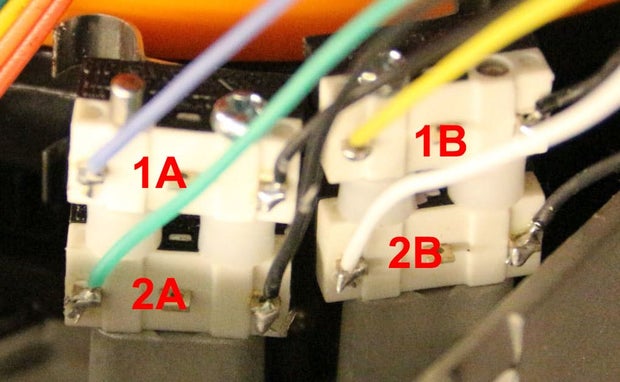
Limit Switches
The Lockitron has 4 limit switches, we will call them 1A, 1B, 2A and 2B as seen in the picture. The black wires all go to ground.
- 1A ----> Metro A0
- 1B ----> Metro A1
- 2A ----> Metro A2
- 2B ----> Metro A3
Here is a diagram of the wiring.
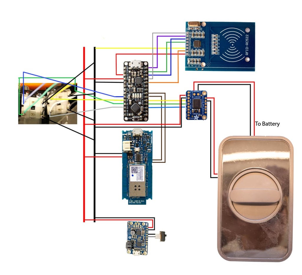
Wiring
Step 5: Setting Up the Arduino MKR1000
We will load StandardFirmataWifi (https://github.com/firmata/arduino) on the Arduino. We then need to make some changes to wifiConfig.h, Make sure Option A is not enabled. We want to use Option B for WIFI_101. Enter in your SSID and password.
Now under the main page scroll down and uncomment SERIAL_DEBUG, we need to get the IP address of our device. Now upload the code and open a serial monitor. Write down the IP address it gives. We need that for writing our app later.
We also now want to comment out SERIAL_DEBUG and upload the code. I found during testing that if serial is enabled the device wont connect to wifi until a serial connection is established.
Step 6: Getting the RFID UID Codes
We are going to need the UID of the rfid cards we will be using. In the Arduino IDE we will need to add the MFRC522 library that can be found athttps://github.com/miguelbalboa/rfid
Once that is installed open the ReadNUID example in the sketch folder MFRC522. Upload that sketch and then open a serial monitor. When you scan a tag you get this displayed.
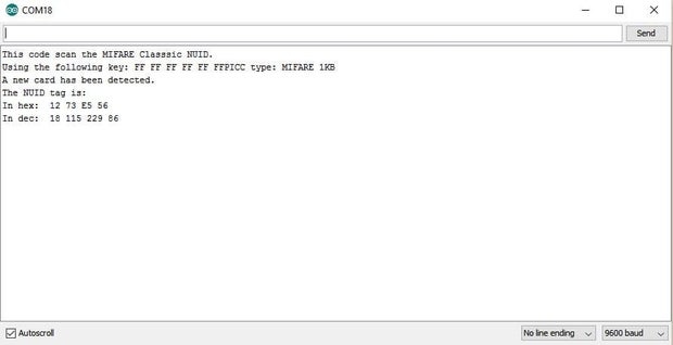
You see that our hex code is 12 73 E5 56, write that down and now scan two more tags. (Your tags will most likely be different, but for this guide we are using the results I got.)
Step 7: Arduino Code Explained
Now open doorcontrol.ino, we will need to change the RFID tag values. Change RFID Tag 1, 2, 3 to the HEX values we got from the previous steps. Look for this section in the code
//Change the HEX values to the tags you scanned
byte tag1[4] = {0x12, 0x73, 0xE5, 0x56}; // RFID Tag 1
byte tag2[4] = {0x02, 0x30, 0xE4, 0x56}; // RFID Tag 2
byte tag3[4] = {0xB2, 0x0F, 0xE5, 0x56}; // RFID Tag 3
When the code is ran it reads the RFID tag. It then compares the UID to the three stored tags. If it finds a match it checks that it is in the correct order. Tag 1 needs to be the first scanned.
// Checks if it matches RFID Tag 1
    if (rfid.uid.uidByte[0] == tag1[0] &
        rfid.uid.uidByte[1] == tag1[1] &
        rfid.uid.uidByte[2] == tag1[2] &
        rfid.uid.uidByte[3] == tag1[3])
    {
      if (tag1count == 0 & tag2count == 0 & tag3count == 0)
      {
        tag1count = 1; // Sets Tag 1 to unlock
Then Tag 2 and finally Tag 3. If at anytime the order is wrong it sets the status back to zero and you need to start over. Similar to how a combination lock works.
Once the program sees the correct combination it will unlock the door. Once the Lockitron moves the deadbolt in it goes back to a starting position. This allows the door to also be manually opened with a key or by turning the knob.
Step 8: Creating the Windows App
I used Visual Studio 2015 to create the app. I followed the Windows Remote Arduino tutorial but made a few changes for using WiFi and for my needs. Things I did different was name the buttons Lock and Unlock and make them larger and easier to see.
<Button Name="LockButton" Click="LockButton_Click" Grid.Row="0" IsEnabled="False" HorizontalAlignment="Stretch" Height="300" FontSize="96">Lock</Button>
        <Button Name="UnlockButton" Click="UnlockButton_Click" Grid.Row="1" IsEnabled="False" HorizontalAlignment="Stretch" Height="300" FontSize="96" Margin="0,10,0,0">Unlock</Button>
I also changed what happens when the button is pressed. I want it to make a pin HIGH but after 10 seconds go back to low.
private async void LockButton_Click(object sender, RoutedEventArgs e)
        {
            arduino.digitalWrite(6, PinState.HIGH);
            await Task.Delay(10000);
            arduino.digitalWrite(6, PinState.LOW);
}
You will also need to change the IP address if using my example to the address you got earlier in this tutorial from your Arduino MKR1000. The reason I am putting the IP address in the code instead of a box that would allow you to enter it in is that when I want to unlock my door I want to make it as easy as possible. I don't want to need to type in an address or remember it.
connection =
new
 NetworkSerial(
new
 Windows.Networking.HostName(
"192.168.1.170"
),
3030
);
I also made a video on the steps I went through to create an app that blinked the Pin 6 LED on and off.
Once I had the code done I created an app package so I could load it on to my Windows Phone I found this tutorial helpful for creating the app package. Once you have the app package created you can run it through the Windows App Certification Kit to see if it passes, this isn't required. It is neat to see though.
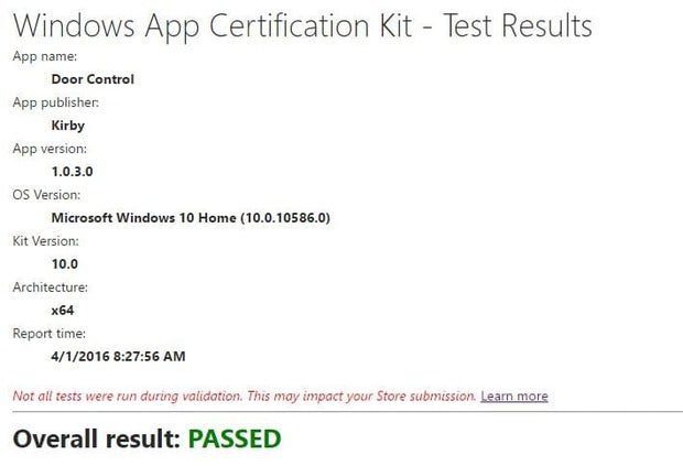
This app passed the test
Step 9: Loading the App on My Phone
Once I had the app I opened settings on my Windows phone and went to the "For Developers" section and enabled developer mode. Under Device Portal it gives a Wi-Fi IP address. Open that link in your web browser on pc.
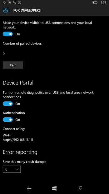
Windows Phone settings

Browser window
At the browser window select your app package that we made previously. Should be in a location similar to
C:\Users\Kirby\Documents\Visual Studio 2015\Projects\Door Control\Door Control\AppPackages Then also select the dependencies. Clicking Add Dependency after you have one selected will add another selection box so you can upload multiple dependencies. Then click Go to upload to the phone. If everything goes good you should see the app on the phone now.
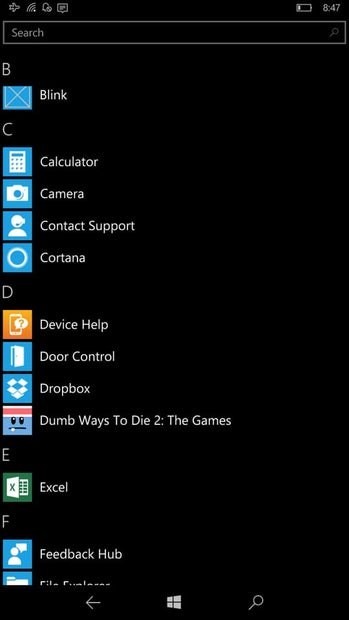
We see the app Door Control now on the phone
Step 10: Using the Windows App
When you use the app it bypasses the need to enter a correct RFID combination. From the app you can press either the Lock or Unlock button. You then have 10 seconds to scan any RFID tag then to trigger the Lockitron.
Step 11: Watching It Work
Here is video of it working with the RFID code and also when using the app. So this project actually works and isn't a concept. Using the Lockitron also allows you to still unlock the door manually.
Step 12: Helpful Links
Here are some links that I found helpful when learning this project.
- https://learn.sparkfun.com/tutorials/lockitron-hardware-hookup-guide
- https://learn.adafruit.com/open-sesame-a-sms-controlled-door-lock
- https://ms-iot.github.io/content/en-US/win10/WRA.htm
- https://msdn.microsoft.com/en-us/library/hh454036.aspx#BeforePackaging
- https://blogs.msdn.microsoft.com/madenwal/2015/11/24/generating-your-tileicon-image-assets-for-windows-10-uwp-using-photoshop-actions/
- https://github.com/ms-iot/remote-wiring-experience
- https://github.com/miguelbalboa/rfid

Participated in the
IoT Builders Contest

Participated in the
Epilog Contest 8

Participated in the
Arduino Contest 2016

![Tim's Mechanical Spider Leg [LU9685-20CU]](https://content.instructables.com/FFB/5R4I/LVKZ6G6R/FFB5R4ILVKZ6G6R.png?auto=webp&crop=1.2%3A1&frame=1&width=306)


