

Introduction: RGB LED Fader BTA3O Class Project


Instead of simulating running a music business, we learned real world skills to create an actual working electronic circuit board. Using the Fritzing program helped us understand the layout of an LED circuit board by making our own designs schematics and PCBs. By using these schematics we were able to figure out the logic of two commonly used ICs. The layouts also taught us how to look carefully for design problems as we assembled the components into their correct placements.
Bottom line for us was that doing something real, making a LED Fader and documenting the process, made learning Information Technology more enjoyable and we did it in a more efficient way.
Jimmy Whelan
Shawn Seguin
Colby Scott
Skylar Wright
Step 1: CD4029 Explained


Discrete electronics aren’t programmed. The circuit is responsible for carrying out “instructions” which are hard wired. Programming uses binary code “1” or “0”. Discrete electronics use a similar process to describe the circuit state as on or off, high or low.
The NE555 sends a clock pulse to the CD4029. The CD4029 advance the count with each clock pulse.
Rules of counting:
1. Binary/Decade counts 0-15 or 0-9 depending on whether it is set high or low.
2. UP/DOWN counts up or down depending if it is high or low.
3. counting starts when PE and CIN are low
4. counting advances with each Clock cycle (pulse from NE555 pin 3)
5. counting stops when COUT or PE are high
6. COUT goes high when the count reaches 15 depending and depending on the UP/DOWN state starts counting down or start counting up.
7. PE can be set high by the circuit such as input from the Q pins or some other input.
8. When PE goes high counting stops is reset to the JAM setting. If PE is allowed to go low counting resumes from the JAM setting.
JAM pins are input pins that can be set high or low depending on whether they are connected to the positive or negative rail. The combination of high and low JAM settings forms a 4-bit binary number. We set the combination to J4 low, J3 low, J2 low, and J1 high. This combines to make the binary number 0001 or as we know it “1”. This is the number that the counter resets to if PE goes high.
Q pins are output pins that are triggered by the clock. The Q pin states are usually used to represent a 4-bit binary number but we are using them to control the behaviour of the counting and to turn LEDs on or off. The 555 timer sends electric pulses to the CD4029 which advances the count and sends electrical pulses to the Q pins. The Q pin states are set to high or low depending on the count. The first three Q pins turn the LEDs on or off, while Q4 is used to set the state of the PE pin to high when the count reaches 8 or binary number 1000. When this happens the counter is reset to 0001 and starts counting up again.
Binary counting table:
Pins J1 to J4 are inputs which can be connected to the positive or negative rails.
| Binnray counting Q4 Q3 Q2 Q1 | Binnary value | Red (LED) | Green (LED) | Blue (LED) |
| 0—0—0—0 | 0 | |||
| 0—0—0—1 | 1 | |||
| 0—0—1—0 | 2 | |||
| 0—0—1—1 | 3 | |||
| 0—1—0—0 | 4 | |||
| 0—1—0—1 | 5 | |||
| 0—1—1—0 | 6 | |||
| 0—1—1—1 | 7 | |||
| 1—0—0—0 | 8 | Counting stopped and reset to: 0-0-0-1 | ||
| 1—0—0—1 | 9 | |||
| 1—0—1—0 | 10 | |||
| 1—0—1—1 | 11 | |||
| 1—1—0—0 | 12 | |||
| 1—1—0—1 | 13 | |||
| 1—1—1—0 | 14 | |||
| 1—1—1—1 | 15 | |||
Step 2: NE555 Timer Explained


The NE 555 Circuit
The job of the NE555 timer is to send a regular pulse to the CD4029 clock pin (pin 15)
Using the Potentiometer and Capacitor, connected to the 7, 2, and 6 pins, it times the pulses coming out of pin 3. The potentiometer allows the capacitor to charge more or less quickly. When the capacitor charge is at 1/3 of the main charge (the main charge is usually that of a battery), it sets pin 3 high. When pin 6 detects 2/3 charge it sets pin 3 low and the capacitor shorts to ground through pin 7, causing the charge to dissipate. Then when the capacitor charge is at 1/3 of base charge it sets to pin 3 to high again, repeating the process. The rules of the 555 timer can be seen below.
Rules of the NE555 Timer in Astable mode.
- C1 is charged through R1, R2, and Vr1.
- When pin 2 detects 1/3 of the base voltage at pin 8, it triggers the timer and makes pin 3 go high
- W hen pin 6 detects 2/3 of the base voltage on pin 8, it sets pin 3 back to low.
- When pin 3 is set back to low the capacitor is shorted through pin 7.
- When the pin 2 detects that the charge has reached 1/3 of the base voltage, sets pin 3 back to high and the pulse is cycle begins again.
Step 3: The Schematic CD4029 Working in Concert With NE555
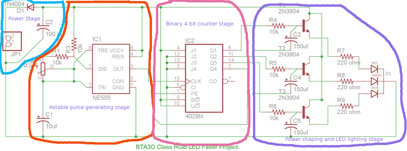


The schematic can be divided into Stages stages: power, 555 astable, Cd4029 decade counting, and the charge shaping stage to give the fade in fade out effect on the LEDS. The ground rail leads back to the power stage and the circuit is fed through the power rail which starts in the power stage. The diode prevents reverse polarity hook up and the capacitor evens out the current. This circuit could run off a 9v battery or a wall brick.
The astable 555 timer stage directs a regular pulse towards the CD4029 from pin 3 which is connected to the CD4029's 15 (clock) pin. The 2 pin starts the pulse when it measures 1/3 of the base voltage, in this case 3v. It stops the pulse when the 6 pin detects 2/3 the base voltage (6 volts).
The counter stage counts in binary mode which generates 4bit binary numbers between 0 and 15. Each bit is sent to any one of the Q pins. A 1 will turn on an LED while a 0 turns it off.
The LEDs fade in and out instead of simply blinking on and off. The 10k resistors cause a delay in charging and discharging of the capacitors and LEDs. of the capacitors.
Step 4: Frizting.org


Fritzing is a step by step process that can be done by anyone. To explain Fritzing I will provide a link http://fritzing.org/download/. Here you can download and try for yourself to see how easy this program is. After downloading program follow these instructions in the step by step list below.
- Open the program. You will be in breadboard view. Here you can place the desired components that you want to use in your circuit. You can also click on the components to change their attributes.
- Next open the schematic tab and you will see all your parts and you will need to organize them.
- Using a schematic as your guide, you will want to start by connecting the parts with wires by clicking on one pin then by dragging that wire to the next desired pin.
- After all your parts are connected space them apart, then put them in an easy to understand placement.
- Now switch to the PCB tab and pick the correct size of board that you will be using.
- Start by figuring out placements for pieces where they will fit on the board but also have space so the wires can fit between the parts.
- Then you will want to connect the parts using the same method of dragging one pin to another, making sure the wires are not overlapping. Make sure not to use auto routing because that will only cause more problems than it will fix (in our experience).
- The next thing to do is to click on routing go down to Design Rules Check (DRC) which will check your wires and placement making sure there are no problems in the design.
- Set your ground fill seeds. We found that having ground fills on the top layer and traces on the bottom layer made soldering a lot easier since some components cover the solder pads on the top layer Note: this issue is avoided completely if you order boards from Fritzing that have through hole plating. Run the design rules again.
- Export for PCB. This will generate solder, etch and silkscreen masks. These are used in the manufacture of the board.
- You can upload your files and they will manufacture a professional grade board in any quantity. Or, you can use the mask to manufacture your own board.
Ordering boards from Fritzing is easy. You can get a quick idea of the cost by hovering the pointer over the Order PCB button. If you want to order PCBs click the button and follow the instructions. Extended prices are important consider since the more PCBs you order, the cheaper the per unit cost is. When designing a board smaller boards are cheaper since they chard by the square inch. Fritzing will even assemble the boards for.
Step 5: Mouser BOM

For this project we will need; DC power connector, Standard LED’s- Through hole, Aluminum Electrolytic Capacitors- Leaded- 16 volts, Aluminum Electrolytic Capacitors- Leaded- 10uF, Metal Film Resistors- Through Hole- 10K, Metal Film Resistors- Through-hole-220 ohm, Rectifiers, Transistors, Counter IC, 555 Timer, Component sockets- 16P, Component Socket- 8P.
| Materials | Mouser # | Price | Quantity | Cost |
| DC power connector | 163-179ph-ex | $1.16 | 1 | $1.16 |
| Standard LED’s- Through-Hole RGB | 604-wp154a4sureqbfzg | $2.00 | 1 | $2.00 |
| Aluminum Electrolytic Capacitor-Leaded- 16 volts | 667-eea-ga1c101h | $0.48 | 4 | $1.91 |
| Aluminum Electrolytic Capacitors-Leaded- 10uF 25 volts | 667-ece-a1cks100 | $0.18 | 1 | $0.18 |
| Metal Film Resistors- Through-Hole- 10K | 660-mf1/4lct52r103j | $0.09 | 5 | $0.45 |
| Metal Film Resistors- Through-Hole- 220 ohm | 660-mf1/4lct52r221j | $0.08 | 3 | $0.24 |
| Rectifiers diode | 512-1n4001 | $0.14 | 1 | $0.14 |
| 2n3904 NPN Transistors | 512-2n3904tf | $0.20 | 3 | $0.60 |
| CD4029 Counter IC | 595-cd4029be | $0.62 | 1 | $0.62 |
| NE555P Timer | 595-ne555p | $0.54 | 1 | $0.54 |
| Component Socket- 16P | 575-199316 | $0.61 | 1 | $0.61 |
| Component Socket- 8P | 517-4808-3004-cp | $0.21 | 1 | $0.21 |
| 470 kohm trim potentiometer | 652-3386P-1-474LF | $1.70 | 1 | $1.70 |
| total | 10.36 | |||
For 1 unit it would cost approximately $10.36. For 50 units it would cost $344.20 making the price of 1 unit $6.88. For 500 units it would cost about $2,620.22 making the price of 1 unit $5.24. So which means the cost of 1 unit goes down the more you sell.
Step 6: Assembly and Design Notes
The etching process went fairly well. We did have to try it a couple of time. The issues were that the iron on transfer using plain photocopy paper was not sharp enough, and there were numerous holes. We switched to photo paper and imediately hade much better results. The next issue was that the board id not platted through holes, so we had to create some vias and jumpers to connect the ground plains on the top and the bottom of the board. We also "tinned a few traces that had thinned out. Component assembly was easy and the board required not trouble shooting. That is the sign of a good design job!
One late innovation was mounting the RGB LED on the "bottom" of the circuit board. This gave us better clearance and a more streight forward battery connection.

Step 7: Analysis
Students comment on learning experience:
How we used the word processor:
We used the word processor to type out the text and tables which we later uploaded to the web site. This required use to learn how to format text, create bulleted and numbered list as well as tables. The bulleted lists and numbered lists helped us to break, analyze and organize our thoughts. It also helped to understand some very complicated concepts such as logic of the CD4029 chip. We are confident that we could use these skills in college or later in our jobs.
How we used the spreadsheet:
Spread sheets were used to help us to generate our bill of materials. Formulas in our spread sheets would automatically tally the bottom line. This gave us lots of freedom to try different scenarios to see how much they cost. The spread sheet also organized our items and their data to keep them readable. The Mouser.com web site has a powerful BOM tool which will import and export spreadsheets. This cuts errors and speeds up creating and updating orders dramatically.
How we used a database:
We did not user Access or OpenOffice Base to design a database. We did use the Mouser database to run queries to locate all the parts of our fader. Mouser has over 30,000 products and over 2,300 development products in stock. Finding a specific product such as a resistor requires using a series of queries to narrow down the option until you can pick the product from a short list. Adding the part to our shopping cart develops an invoice. The invoice is actually a database report. The mouser database also export spread sheets through its BOM tool. We can now create a BOM from a schematic and investigate extended costs.
How we used CAD software:
We used computer assisted design (CAD) software. What we used was called Fritzing. Fritzing.org is a free open source software circuit design CAD program. It is very easy to use. It also gives the option of manufacturing you PCB. The biggest challenge was routing the traces on the PCB. Also trying to get an efficient design, that was as small as possible, was not easy. Some design considerations did not become evident until we soldered the first PCB. We also realized that the LED and potentiometer could be mounted on one side and rest of the components on the bottom. This gave us uncluttered access to the potentiometer and LED. We found the process of designing PCB very interesting. Some of us would pursue this as a job or more likely as a hobby.
How we used communication software:
First off we used web mail to transfer documents and images to the teacher form our class projects that we had created beforehand. Then we uploaded the images and files to this website using the on screen instructions. Using this means of communication is an easy way to transfer information online. We can also collaborate on a single project such as this instructable and achieve a better results as a group. The plus side of using communication software is that you don't need to be in the same room or do it all at the same time to achieve a group effort. Having multiple sets of eyes reviewing our work catches mistakes that we might otherwise have missed as individuals and it is easier to accomplish efficient brainstorming as a group. All in all we find that having communication software in this day and age is a great advantage to making more efficient progress in a timely manner.
Teacher's Comments:
This activity was originally conceived as a way of integrating authentic learning into a BTA3O class I was teaching. The course is a business computers application course. The general concept of the course is for students to demonstrate their skills by taking on the role of a music store owner and then generating a stream of business correspondence, spreadsheets, a database, and a web site. The course shows it age by using a music store as its premiss iTunes irrevocably change the music retail business. This fact alone made my students disinclined to engage meaningfully in their learning. Other aspects were evident such as the dated technology cited in the course and the course, predating Google docs, is out of step with how technology is used today.
Thus it was agreed that we would construct something concrete, with an eye toward creating a salable product. The process of designing and documenting the product entailed using the following: word processor, CAD software, spreadsheets, an online database, email, web based storage,and web based web page authoring.

Participated in the
Gadget Hacking and Accessories Contest


