

Introduction: Raspberry Pi Pico With I2C Oled Display and CircuitPython


This is my first experience using this little board from Raspberry Pi Foundation.
I preferred to install CircuitPython on the board, but I came across the lack of usage examples (because the board was just released, obviously). Many of the examples on the Adafruit website have not yet been ported to the new board, so I am experimenting and making the necessary adaptations.
As they work, I'll share them here.
First, install CircuitPython in your little board. Just follow this guide:
https://learn.adafruit.com/getting-started-with-ra...
Second, download the CircuitPython Library Bundle:
https://github.com/adafruit/CircuitPython_Communit...
Third, install your favorite IDE (I preffer Thonny, but Adafruit indicates MU).
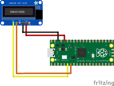
The connection is as simple as follows:
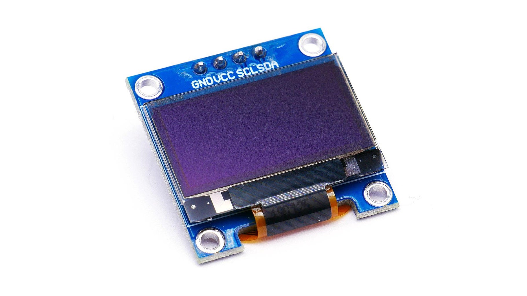
SSD1306 | Pico
VCC ---> Pin 36
GND ---> Any GND available
SDA ---> Pin 6 (GP4)
SCL ---> Pin 5 (GP5)
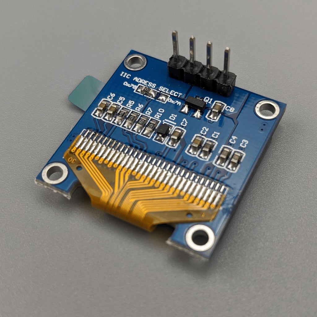
On the back of the Oled board there is an address indication and a jumper. In the case of my card, the addresses indicated are 0x7A or 0x7B. None of them work. The correct would be 0x3C.
In the Adafruit guide https://learn.adafruit.com/getting-started-with-r... there is an indication that calls to the I2C bus are executed through the BUSIO module.
No Default board Devices
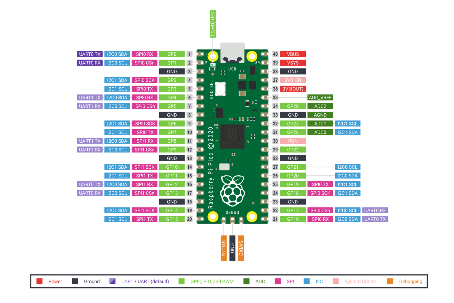
The Pico does not label specific pins as the defaults to use for I2C, SPI, or UART connections.
I2C Example
To setup an I2C bus, you specify the SCL and SDA pins being used. You can look for "SCL" and "SDA" in the pin names in the pinout diagram above.
So, I use the code:
import board

import busio

i2c = busio.I2C (scl=board.GP5, sda=board.GP4) # This RPi Pico way to call I2C<br>
Supplies
1x Raspberry Pi Pico -
https://www.adafruit.com/product/4864
1x SSD1306 Oled I2C display (128x64 resolution) -
https://www.amazon.com/Diymall-Yellow-Arduino-Disp...
CircuitPython for Raspberry Pi Pico -
https://circuitpython.org/board/raspberry_pi_pico/
Adafruit CircuitPython Library Bundle -
https://github.com/adafruit/Adafruit_CircuitPython...
Thonny IDE
or MU
Step 1: Full Code
The second piece of code I've found in this other guide:
https://learn.adafruit.com/adafruit-oled-featherwi... So, I've changed two things: the display resolution and I2C call...
# Adapting the example in https://learn.adafruit.com/adafruit-oled-featherwing/python-usage
# to use with Raspberry Pi Pico and CircuitPython
import board import busio import displayio import terminalio import adafruit_displayio_ssd1306 from adafruit_display_text import label
i2c = busio.I2C (scl=board.GP5, sda=board.GP4) # This RPi Pico way to call I2C
display_bus = displayio.I2CDisplay (i2c, device_address = 0x3C) # The address of my Board
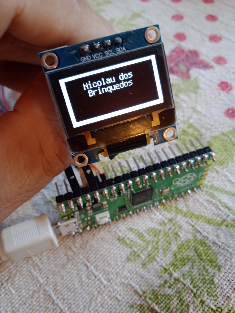
display = adafruit_displayio_ssd1306.SSD1306(display_bus, width=128, height=64) splash = displayio.Group(max_size=10) display.show(splash)
color_bitmap = displayio.Bitmap(128, 64, 1) # Full screen white color_palette = displayio.Palette(1) color_palette[0] = 0xFFFFFF # White bg_sprite = displayio.TileGrid(color_bitmap, pixel_shader=color_palette, x=0, y=0) splash.append(bg_sprite) # Draw a smaller inner rectangle inner_bitmap = displayio.Bitmap(118, 54, 1) inner_palette = displayio.Palette(1) inner_palette[0] = 0x000000 # Black inner_sprite = displayio.TileGrid(inner_bitmap, pixel_shader=inner_palette, x=5, y=4) splash.append(inner_sprite) # Draw a label text = "Nicolau dos" text_area = label.Label(terminalio.FONT, text=text, color=0xFFFF00, x=28, y=15) splash.append(text_area)
text = "Brinquedos" text_area = label.Label(terminalio.FONT, text=text, color=0xFFFF00, x=32, y=25) splash.append(text_area) while True: pass
Attachments


Participated in the
Microcontroller Contest


