

Introduction: Recordable Communication Device (Aided AAC)


For this project, our goal was to create an Augmentative and Alternative Communication (AAC) device for a child named Garek who has Cerebral Palsy and is nonverbal. The communication board will be tailored to the child's specific needs and preferences. The board will be designed to be easy to use and understand, with clear and concise visual cues, and will be adapted to suit the child's motor abilities and communication style. The ultimate aim is to empower the child to express themselves more effectively and confidently, and to enhance their overall quality of life by enabling them to participate more fully in everyday activities and social interactions.
Note: We went through two iterations of this product.
Step 1: Research
After conducting thorough research on various AAC technologies for children with Cerebral Palsy, we engaged in discussions with Mrs. Larcom to comprehend the objectives of this project in relation to Garek's needs. Through this, we gained valuable insights about Garek's unique personality, interests, and communication challenges. We also had the privilege of meeting Garek's speech therapist, Jodi, and observing Garek's interactions in person. During our discussions with Jodi, we were able to obtain detailed information about Garek's speech goals, areas of difficulty, sensory overload tendencies, and his past experiences with various AAC boards. This information served as the foundation for us to finalize our research and begin prototyping different communication board options.
By utilizing the knowledge we gained through our research and discussions with Garek's family and therapist, we aim to create a communication board that is tailored to Garek's specific needs, preferences, and communication style. Our goal is to design a board that is easy to understand, simple to use, and optimized for Garek's motor abilities. Through this project, we hope to empower Garek to communicate effectively and confidently, improving his overall quality of life and enabling him to participate more fully in everyday activities and social interactions.
Step 2: Initial Design Process


Initially, we wanted to make a communication board with buttons that Garek could push. These buttons would have pictures and words on them. Once the button was pressed, a sound saying that word would play. Some prototype designs can be seen above.
After meeting with Garek, his family, and his speech therapist, we found out that Garek has a limited range of motion and that it is much easier for him to grab and activate a floating button that is on its side, rather than push a button down. With this in mind, we decided on the design that is drawn above.
This design has a wooden base that holds all the electronics such as the battery, the recording module, the power switch, the charging port, the speakers, and the breadboards which connect everything together. Then we will have 3 metal goosenecks coming out of the box and holding the buttons. Each gooseneck will have a record button and microphone behind them which connect to the button so the button sounds can be changed. The buttons also have a glass cover where pictures can be placed in the buttons.
Step 3: Supplies
- 2x ISD1820 Sound Module 3pk
- Tactile Switch Buttons 10pk
- Adafruit Battery Backpack
- 3.7V 4400 mAh Lithium-Ion Battery Pack
- Mini Solderable PCB Board
- 24 Gauge Electrical Wire
- Adafruit Lithium Ion/Polymer Charger
- 3x 15.7’’ Microphone Gooseneck
- SPDT Slide Switch
- 3x 1-¾ in. OD. X 1-¼ in. ID. 24in Vinyl Tube
- VELCRO Think Clear Fasteners
- Adhesive Rubber Pads
- USB-C Cable
- Microphone Flange Mount
- JST-PH Battery Connectors
- Head Cap, Screws, Bolts, Nuts Assortment Kits
- 3W Power Amplifiers
- 3W 8Ohms Speakers
- 3x Jelly Bean Button
- 10' x 3/8" & 1/2" Split Flex Tubing
- 2x Hinges (Around 2 in. in length and width)
- 2x Trigger Clamps
- Black and Green Spray Paint
- Plywood
- Wood Glue
Tools Used
- Laser Cutter
- Heat Gun
- Drill
- Soldering Iron
- Misc. Hand Tools
Step 4: Fusion 360 Designs of First Prototype


Design Requirements:
- It must be able to fit on a try
- It must be safe for Garek to use
- It must be stable enough to support the 3 goose necks
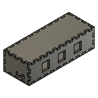
After determining the requirements for the AAC device, a Computer Aided Design (CAD) of the parts we will need to cut out of the Medium Density Fireboard (MDF) board. Here we have the Fusion 360 designs of the base box and the mount for the buttons. We went through several redesigns to finally reach this point.

Step 5: Constructing of Base


After we had the design in Fusion 360, we converted the files to DXF. We opened the files in Inkscape to adjust the canvas size, rearrange the pieces, and adjust the stroke for laser cutting. Then, we saved the file as a PDF. We used the Epilog Fusion Laser Cutter to cut our designs out of a wood panel. Before printing, we made sure our canvas size was correct, and changed the vector setting to 1% speed, 100% power and 50% frequency. Furthermore, we had to readjust the job and focus of the machine and also turn on two vacuums. Due to the type of panel we currently used, each piece needed two passes for the laser to cut all the through.
Step 6: Sound Module Rewiring


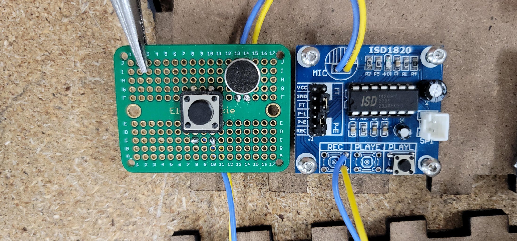

Next step is to unsolder and remove the microphone, REC button and PLAYE button. Then, solder on 24 AWG wires on just the slots where the microphone and REC button were. For the REC button, only two wires are needed and positioned vertically in either side as depicted above. The PLAYE button replacement will be mentioned here later on.
Step 7: Upgrading Speakers

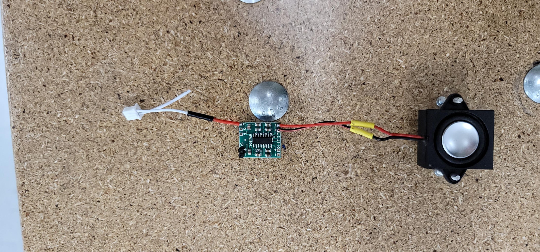
Then, to boost the sound output of the module, consider soldering both the 3W power amplifiers and 3W 8Ohm speakers together because the module's included speakers may not provide sufficient volume. For the amplifier, since we are using 3 separate speakers for each module, pick either the left or right output as preference. With the original white output wire packaged with the sound module, use a wire cutter to cut and combine the positive side of the white wire with a 24 AWG wire so that it does not break off as easy. Then, use the provided heat-shrink tubing to securely seal the two wires together and solder the positive end onto the L slot that is found next to the 5V power supply.
To find out which side is positive for the original white output wire, plug it into the sound module. The positive side is the top side when looking at from the logo, ISD1820.
Step 8: Main Power Supply


Connect the battery to the charger's LiPo Batt port and the charger's Load Out port to the small battery backpack. Then solder a stable connection from the backpack's ground and battery hole to the main breadboard used to share power to all the components using the included PCB connector. As depicted above, we made several 24 AWG wire connections to spread the power into multiple terminal strips on the breadboard. On those individual strips, the backpack's ground hole is used as negative while the battery hole is positive. Then, we soldered four M-F breadboard jumper wires for each of the pair of positive and negative terminal strips which will each power the sound module and amplifier.
Step 9: Initial Electronics Testing


For each of the jelly bean buttons, we soldered two 24 AWG wires to just two of the button's connector. Then, reassemble the buttons and fix the wires neatly onto the gooseneck using split flex tubing.
For the assembly of the whole device, we connect the button's wires to the sound module's PLAYE ports. Only one of the vertical pairs are needed. Then, on each section of the four M-F jumper wires from the power supply, we connect the corresponding pair of positive power to the sound module's VCC and amplifier's 5V positive hole and pair of negative power to the sound module's GND and amplifier's 5V negative hole. We tested the input and output of both the extended REC button and jelly bean button.
Step 10: Fitting Screw on Base


According to the layout of the current CAD design of the box, we positioned the circuits in a way that we drilled holes onto the bottom and speaker side of the box as depicted above. We needed to fit screws onto each of the three sound modules, main breadboard power supply, and charger module for the bottom side. For the speaker side, we needed to fit screws onto each of the three speakers.
Step 11: Initial Assembly of First Prototype
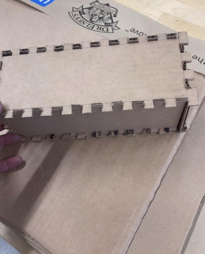


We first started with a cardboard prototype of the box that allowed us to get a better scope of how the positioning of the different electrical components will be. From the final CAD of the box, the height was reduced.
With the final design cut out, we temporarily assembled it before gluing to see how it looks.
Mounting the Buttons
With gooseneck mounts connected to the goosenecks, we drilled two holes that match the size of the mount's hole onto the top of the box. We drilled three holes on the perimeter of the CAD button mount to match the actual button's back outer holes and screwed them together. Then, we add adhesive to the mount add to the stability of this connection. On the top of the box, we drilled a larger hole for the gooseneck to allow the wires to go through the box and onto the incased circuits.
Mounting Record button and the Microphone
When the gooseneck placements were secured the recording and microphone on the underside of the top part of the box. We had the record button sunken into the box to help prevent the button from getting pressed.
Electronic Placement
The CAD design for the box incorporated a place for the charging port, placement for the speakers, and three holes on top where the goose necks. Each soundboard module is to be mounted behind a speaker and under one of the goose necks.
Rubber Pad
Lastly, two large rubber pads were then stuck onto the base of the box to provide more stability when the finished box is to be settled down onto a flat surface area like a table.
Step 12: Spray Painting Box


After cleaning up the panels, we spray-painted the case with a base coat of black, followed by lime green decals and a final clear coat. To paint the designs, we used a combination of masking tape and custom stencils cut from cardstock. Paint was applied in multiple thin coats for even coverage and a durable finish.
Step 13: Final Assembly and Testing of First Prototype


With all the components soldered, connected, and spray-painted, we fully assembled all the pieces together. The electrical components are screwed into their rightful spots. Next, we glued all the sides but one, which allows the user to open up the box and possibly fix any potential problems or look inside. This side is opposite of the speaker and is held on by four nuts that is screwed in reverse onto a block of wood we glued inside for stability.
For testing, we turned on the switch to see if it both glued in its slot and work as intended, pressed the record button on top and voice a word, and pressed the three buttons to ensure they are outputting the word captured by our voice. Finally, we charged the device with its USB-C cable.
Step 14: Printing Symbols


The speech therapist had provided images of the symbols they used for Garek's current learning. We increased the image size to make the symbols similar to the approximate size of the buttons for better visual clarity when placed into the button.
Step 15: Initial Delivery of First Prototype
Upon meeting with Garek and his family, we stapled Velcro on to the bottom of the box and used the adhesive side to stick the other piece of Velcro onto Garek's tray. He was delighted to try out the box; however, he had gotten much stronger since our initial meeting with him, and the gooseneck design proved to be too delicate for his current physical ability; he was able to pull the button housing from the gooseneck. We discussed with the family what would be the next step and came up with a solution to make the box longer in length, remove the gooseneck, and screw in the buttons on the top of the box.
Step 16: Fusion 360 Design of Final Prototype
Design Requirements of Final Protoype:
- It must be able to fit on a try
- It must be safe for Garek to use
- It must be able to fit all three buttons
- The buttons are separated just enough for Garek to reach and press
After determining the requirements for the AAC device, a Computer Aided Design (CAD) of the parts we will need to cut out of the same Medium Density Fireboard (MDF) board. Here we have the Fusion 360 designs of the longer base box which is similar to the previous structure before.
Attachments

Step 17: Slight Changes


Since we have a longer base to work with, we had to increase the wiring of several components to both reach inside other hardware and outwards whenever the user needs to examine the insides or fix some issues. There are also two hinges installed in the top versus having internal wood pieces glued to the sides for screws to be installed in the back of the box. This allows the user to have a more easier way to access the internals when necessary. There will also be an extra wooden slab in the back with the speakers that is glued and used as a way to clamp the box on to Garek's tray.
Step 18: Final Assembly and Testing of Final Prototype


After resoldering and rewiring components again, we simply placed all of them together in a similar structure/design as previous mentioned before. The only difference is the goosenecks are removed, jelly bean buttons are screwed directly on top of the box, and our base box is larger that before. The opening of the box is readjusted to be opened from the top of the box instead and is kept together with two hinges while the other pieces are glued together. On the speaker side, the extra wooden piece is glued and screwed together.
For testing, the box is tested using previous steps and works as designed.
Note: We encountered a previously unseen error while testing in which a message from one of the buttons would loop endlessly upon turning the device on. We were unable to reproduce the error, but we found that opening up the case and pressing the PLAYL button located directly on the affected ISD1820 module while the device is on will stop it.
Step 19: Final Delivery
This time the product is delivered to Garek's home as it is very similar in design of both the box and circuits. The buttons are screwed to the top which poses no issues for its durability compared to the gooseneck version.


![Tim's Mechanical Spider Leg [LU9685-20CU]](https://content.instructables.com/FFB/5R4I/LVKZ6G6R/FFB5R4ILVKZ6G6R.png?auto=webp&crop=1.2%3A1&frame=1&width=306)


