

Introduction: Reese's Power Bank - Laptop and Smartphones


Hi All
My name is Dani, and this will be my first instructable :) Hope this won't be my last.
I'm excited, and I hope you will find my project fun and useful.
I had this idea for quite some time, just did not have the time until now. Actually one of the reasons to write here is to have an incentive not to procrastinate the projects indefinitely.
So, what are we doing here? The final product is a mobile power bank to power your laptop and various stuff that will charge out of USB. It has a 4s2p 5000mAh inside battery, with balance charging board and voltmeter to monitor the status of the battery. One laptop plug with 19V out, two USB 5V outputs and laptop jack to charge the whole package. I find the packaging funny, but it is actually convenient to carry in side pocket of a backpack.
Let's get started and I hope you enjoy.
When researching this topic I found several guides on the net, but they were all somewhat lacking or resulted in something that is stationary and not useful as carriable product. I hope this guide will fix that.
Step 1: Component List and Basic Layout


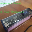
The basic layout is shown on the first picture. Here is the component list:
1. Reese's Snack Mix (we just need the box) - from your favorite grocery store.
2. LiIo cells, I'm using 18650 size LG cells. Bought them from ebay seller original_year. I can highly recommend those. They arrived very quickly, came matched and perfectly balanced. I also find his prices very reasonable. Just an advice, buy good cells from a reputable source, this is the heart of your power box and you don't want to cut corners here:
https://rover.ebay.com/rover/1/711-53200-19255-0/1...
3. Balance board, I used this one from BG:
www.banggood.com/4A-5A-4-String-18650-Li-ion-lithi...
But feel free to use something else.
4. Step up board, I used this one from ebay:
https://rover.ebay.com/rover/1/711-53200-19255-0/1...
This one is good because it allows for higher currents.
5. USB step down board, this one from BG:
www.banggood.com/Dual-USB-9V12V24V36V-to-5V-Conver...
6. LCD voltmeter, this one from BG:
www.banggood.com/18650-26650-Lithium-Li-ion-Batter...
Some wire, shrink, push button and tools which I assume you already have.
We are going to run 8 18650 LiIo cells 2500mAh each. They will be connected as 4 in series with 2 parallel in each. It is very important to charge Lithium cells with balancer (or smart charger) because we are using simple laptop charger. The total output, 14.4V nominal, will be once put through step up circuit to 19V which will charge the laptop. Second will go through step down with dual USB output for your smartphones and such. I addition I'm adding a voltmeter to monitor the battery, this is hooked up through push button, because it is not needed all the time.
Step 2: Soldering the Cells and Fit Check


I soldered each two cells in parallel and then connected in series.
Used thick enough wire (14 or 16 awg, don't remember) to handle the currents.
One note about soldering cells. I used to sand small area on the poles to have better connection. And then I tried once without, I've found out that the solder is just as good, just use a proper amount of paste.
Make sure to leave leads to the balancer board.
Also, whichever box you will be using, try to fit everything inside. I ended up with block of six cells with two on top in diagonal.
Add female jack to charge your big battery.
Step 3: Lid Matters


Unfortunately I did not take pictures of the lid fitting process, so here is just the final product.
I've fitted the voltmeter, push button, charging jack and the output plug into the lid. It is pretty straightforward, just make sure no physical interference in the box occurs. One thing to note is that the lid is very flexible, so I used a piece of a PCB board to stiffen it.
Step 4: Step Up and Step Down


Next step is to solder in the two output boards.
Maintain proper isolation, remember you will tackle everything in small space. Always check physical fit.
I used shrink and hot glue for isolation, also put a thin layer of foam between the two batteries floors.
The USB outputs are looking sideways.
One more thing, I removed any available bolt in connectors from the boards and soldered all the leads directly. I'm looking for durability and don't want to tighten the bolts down the road.
Step 5: Put Everything In


Everything is connected outside, functionality checked.
All goes inside and immobilized with foam.
I fixed the USB board with hot glue, it is important to plug in cables so the glue won't go anywhere where it is not supposed to.
Everything had a tight fit, but eventually closed as it should.
Step 6: Functionality and Final Remarks


All works as it should, I'm really happy with the result.
If I would do it again, I would probably opt for slightly bigger box or do better architecture inside.
The USB board fixing does look a little sloppy with the hot glue.
The voltmeter displays the voltage with button pressed, this is done intentionally. Also I connected it before the step up so it will display the main battery capacity.
The step up board has small potentiometer to adjust the out voltage, after I set it to 19V, I fixed it with hot glue, just in case.
The voltage monitor has small button which allows voltage adjustment, it was set to 14.4V - 4s nominal voltage.
That's it, hope you enjoyed it as much as I did.
Dani


