

Introduction: Remote Weather Monitoring and Ground Reception of Satellites Using SDR and Intel Edison


This article explains a project on Remote Weather Monitoring and Ground Reception of Satellites. The reception of APT Satellite Signal data (to be explained in a short while) was accomplished by leveraging the power of Software Defined Radios. This signal data which has a very high sampling rate and every element of data received from it is critical for that satellite pass period. Since a prototype setup like this (working around 137MHz) demands good elevation and an unobstructed view of the sky, it is not feasible to have a processing station right where the antenna is located. To overcome this, an Intel Edison's processing and connectivity capabilities was made use of. The constantly received signal data was then transmitted over a TCP server to the base station.
To know more about satellite transmission, data acquisition, access to real time precise and reliable information being transmitted over a frequency channel from a satellite the predictive analytics and other use cases that can be derived from this source of structured data in a world where data has attained utmost importance and to know how this was built by using a Software Defined Radio and the different antennae, continue reading.
End to End Hardware Setup for Satellite Reception using Intel Edison and Software Defined Radio from Rajesh S on Vimeo.
Step 1: Weather Satellites: Data Acquisition and Analytics

We've all seen weather forecast images. Especially during those thunderstorm season when you choose to check for forecasts before heading out.

Ever wondered how these images are generated? The data acquisition and analytics from an eye in the sky? This is a brief of how that works.
There are various kinds of satellites. Geostationary (rotates at the same speed as earth and constantly over a particular location), Polar orbiting, Communication satellites, Astronomy satellites (Hubble), Navigation satellites(GPS) and so on. Similarly, there is one specific set of environmental satellites used for weather monitoring. Some examples of Weather satellites are NOAA 15 , NOAA 18 , NOAA 19 and Meteor M2.
National Oceanic and Atmospheric Administration's (NOAA's) have different satellites for weather imaging and analytics. These were developed by NASA. NOAA N was developed to collect information about Earth's atmosphere and environment to improve weather prediction and climate research across the globe. There are three types of satellites but as far as this prototype is concerned we focus on the polar orbiting satellites NOAA 15,18,19 and Meteor M2.
The above mentioned satellites have a circular orbit that permits uniform data acquisition and also ensure that data for any region of the Earth is no more than six hours old.The polar orbiters are able to monitor the entire Earth, tracking atmospheric variables and providing atmospheric data and cloud images.
The NOAA Satellite and Information Service provides timely access to global environmental data from satellites and other sources to monitor and understand our dynamic Earth. This data has also been used largely for Data Visualization, Predicting patterns in weather and Data analytic use cases.
The satellites transmit the satellite imagery pictures via APT WFM radio waves at around 137MHz.(Every satellite has it's own unique frequency at which it broadcasts). The best part is that this data acquisition can be done by leveraging the power of Software Defined Radios and a remotely connected device with processing capabilities like Intel Edison since the antenna setup needs to be in a location with unobstructed aerial view.
Once we intercept these APT ( Automatic Picture Transmission) waves at 137MHz frequency, we sample the wave and then use a decoder to obtain the satellite image.
https://en.wikipedia.org/wiki/Automatic_picture_tr...
This project is supported by BAL-IoTLAB (www.iotlab.in)
Step 2: Components Involved in Building This Prototype


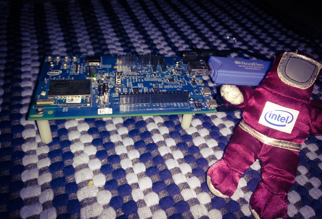
- Software Defined Radio ( NooElec SDR Mini 2 RTL SDR) - for reception of WFM 137 MHz waves
- Intel Edison - for processing and transmission of data from prototype antenna and setup location
- 12V Lead Acid Battery/ AC Source of power at antenna location.
- Any antenna with adequate gain and tuned to 137 Mhz frequency.
For this prototype we experimented with 3 different antennas listed below for stronger reception and also to analyze the variation in quality of signal received at the elevation (terrace of a 2 floor building). The prototype setup could be built with any one of the three antennas.
The antennas that were used while constructing this prototype were:
- A DIY Quadrifilar helix (QFH) antenna
- A 3dB (5/8) lambda Ground Plane VHF Antenna tuned to 137.5 MHz using a miniVNA network analyzer. (SWR around 1.05)
- A 6dB 2x(5/8) lambda Ground Plane Antenna
S/W tools:
- GPredict to determine the time and trajectory of the weather satellites as observational recordings have to be made only during satellite passes over a region.
- Gqrx - An SDR receiver tool that provides a spectrum visualizer as well. This tool also allows control by connecting to the Intel Edison for remote observation data transmitted over a TCP connection.
- Wxtoimg - Decoding the audio wave, Overlay maps, Finer weather details from the received signal.
- Sox - A Linux based tool for audio processing and re sampling received signal at a different rate suitable for decoding.
PS: A handy app like https://play.google.com/store/apps/details?id=com.runar.issdetector&hl=en could also be used for alerts and tracking satellite passes throughout the day.
Step 3: Connecting the SDR to Intel Edison and Initial Configuration

Since it uses an USB interface it can be directly interfaced with Edison that offers out of the box USB capabilities. Once we connect it to the Edison we will have to configure it to run as a device that can transfer the signal reception data from the antenna location to a Linux PC Host running Gqrx over TCP.
- Connect the SDR to the Intel Edison through the USB port
- Ensure that the microswitch is towards the USB port as this is the mode that allows to power the USB device connected to the interface
- Connect the USB cable between the PC and Edison to the outermost micro USB port. We will use this to establish the serial connection needed for programming.
- Also, the Edison would need to be powered with a 12V adapter/lead acid battery to meet the power requirements of the SDR.
- Setup a terminal session using Putty with the appropriate Serial Line and 115200 baud rate
- Login into Edison using your credentials
- Connect to Wi-Fi using
configure_edison --wifi - libusb is a dependency needed for interfacing the SDR with Edison but the default repositories do no have this. To configure Edison to fetch packages from a different repo that is unofficial but contains libusb, use these commands
vi /etc/opkg/base-feeds.conf
Inside the VIM editor press I to Insert, Replace the existing repo contents with the follwoing
src/gz all http://repo.opkg.net/edison/repo/all
src/gz edison http://repo.opkg.net/edison/repo/edison
src/gz core2-32 http://repo.opkg.net/edison/repo/core2-32
Then run this command
opkg update
Now install libusb using
opkg install libusb-0.1-dev #Also install git if not already present
Step 4: Antenna 1: Quadrifilar Helix (QFH)


The first antenna that was experimented with was a QFH antenna. This was built using
- PVC Piping for the framework
- RF Coaxial cable
- Solid 12 AWG Copper wire
- PVC Cap for waterproofing
- Connectors
In this build I used a BNC Male connector at the point where the Coax terminates from the antenna. And then a BNC Female to MCX Male Connector to connect it to the Nooelec SDR which has a MCX Female port for antenna.
In the initial stage, after building the antenna experiment with the antenna and test it by directly connecting it to a PC instead of the Edison Remote Reception method explained later to be sure that the soldering and construction is correct.
The dimensions of the QFH antenna needs to be accurate and this is computed using the wavelength requirements corresponding to the frequency of 137 MHz. For framework construction DIY instructions use this guide http://www.rish.kyoto-u.ac.jp/digitalbeacon/inform...
Step 5: Antenna 2: 3dB (5/8) Λ Ground Plane VHF Antenna


In order to get more accurate and stronger reception of the signal, for the next stage of the prototype setup was built and setup with a 3dB ground plane antenna. This antenna comes with adjustable length that allows frequency tuning based on use case.It is a high gain antenna and the radiation pattern is also a omni-directional one.Using a miniVNA Vector Network Analyzer and a software tool to determine the SWR for different frequencies for a given length, the antenna was tuned for reception at 137.5 MHz which is the median frequency of all NOAA Satellites.
This is suited for VHF reception and allows good signal reception at higher elevations.
NOAA 15 Recording using 3dB Ground Plane Antenna from Rajesh S on Vimeo.
Step 6: Antenna 3: 6dB Ground Plane Antenna


In order to go one step further, and attempt reception of Meteor M2 ( a satellite known for high res weather imagery) along with NOAA weather satellites the next antenna used in the prototype setup was a 6dB 5/8 wave Ground Plane antenna. Since the experimental setup was made at above four floors above ground level, at this kind of elevation using a high gain antenna becomes critical. To know more about the ground plane wave antennas, comparison and the technical aspects read through http://www.boat-project.com/tutorials/vhfant.htm . The best reception results were obtained with this particular antenna.
The 6dB Ground plane antenna after assembly

The RF connectors that were used with the 6dB (5/8) wave Ground Plane Antenna to interface with the SDR are shown in the images below. An Antenna end to SMA connector followed by a SMA to MCX male connector which connects to the MCX present on the NooElec Mini 2 SDR
Antenna connector terminating in SMA

The SMA to MCX connector

The result of combining the two connectors


Step 7: Understanding When to Record Signals From Satellites


A software tool available for Linux and Windows called GPredict was used to track satellite positions. Since this methodology requires signals only when there are satellite passes above the region where the prototype setup has been constructed, this step becomes critical to take readings at the right time. An alternative to this would be to Update Keplers and check " Satellite Pass List" Wxtoimg tool that will be used later for decoding the image.
On Ubuntu install GPredict using
sudo apt-get install gpredict
Once installed, start GPredict by typing gpredict in a terminal window on Ubuntu.
To setup GPredict, Add your observation location under settings. Then go to File> Add new module.
Add NOAA 15,18,19 satellites to the list of satellites that we wish to record signals from, after creating the module it should look like the attached screenshots.
Once this is done, go to Edit > Update TLE > From network. This ensures that the tracking details are up to date. Now you can see when the next satellite pass is as shown in the window. Each satellite has around 3 to 4 passes a day atleast and lasts for approximately 10 minutes. So make sure that you take the signal readings for the appropriate satellites during those intervals (satellite pass period).
Step 8: Recording Signals From Satellites


We record the signals using the GQRX tool for Linux. It has a spectrum visualizer and inbuilt support for receiving signals over a TCP server.
Get the tool and install it from http://gqrx.dk/
To get familiarized with the options available in the tool based on the SDR being used and also to check the strength of signal from the antenna being used and ensure good signal reception by the constructed antenna, first experiment with the tool by connecting the SDR directly to a Linux PC and using the tool with the settings shown in the screenshot, rather than receiving data over TCP right from the very beginning.
The instructions to receive signal data from a remote location over TCP using an Intel Edison are included in the later steps.
Vary the averaging and sampling rates by trial and error. This slight adjustment could result in a better signal.
Sample rate of 2.4MSPS atleast is recommended. The recording is made on WFM Stereo mode. You might have to toggle to AM or any other option and then WFM to be able to hear it on the PC audio out.
Set Gain to maximum or around (42.1 dB) varies based on antenna and SDR being used.
When the signal is being received from the satellite you will hear a distinct audio and several peaks within a bandwidth of 36k and a dotted line pattern below the spectrum. The audio gets distinct as the satellite gets closer and closer. The frequencies of the satellite transponders are :
- NOAA 15 - 137.5 MHz
- NOAA 18 - 137.9125 MHz
- NOAA 19 - 137.1 MHz
These frequencies may vary slightly due to Doppler effect shifts, so use the frequency tuner at the top of the GQRX window to vary this tuning. Once you notice the peaks, adjust the Bandwidth so that all the peaks fall within the filter (greyed out portion) and the audio is distinct. This Bandwidth/Filter Width is around 36kHz.
To record the signals being received in realtime there is a Rec (Record) option under the Audio tab of gqrx. By setting the location for save files, the audio wav files can be logged and saved for further resampling and processing. Ensure that the gqrx settings match those in the snapshots.
More information and technical details of these settings are available on the Gqrx website.
The windows equivalent tool to perform the above process is SDR# and offers similar options for receiving signal data over TCP as well. The settings for using SDR# is summarized in a video in the upcoming steps. Also, the embedded videos in this instructable contain signal recording observations to give you an idea of the audio and waveform seen when a satellite pass is occurring for reference.
Gqrx NOAA 18 recording sample with DIY QFH antenna from Rajesh S on Vimeo.
The audio wav file from GQRX/ SDR# recorded during the satellite pass period ( known from GPredict) is subjected to further resampling and decoding in order to obtain the weather imagery.
Step 9: Setup Remote Signal Receiver Using Intel Edison


Weather monitoring and Satellite Signal Reception depends an unobstructed view of the sky and setup at a considerably elevated structure for stronger signal reception. Due to these factors directly connecting the SDR to a PC is not feasible. To overcome this we can use the Intel Edison as a TCP server to transfer the satellite signal data from the location of antenna setup to a base station running GQRX which would be saving this data and perform the decoding on the received signal data.
So far, interfacing the antenna with the RTL SDR directly connected to a PC has been covered and experimented with. Now we will use an Edison connected to any WiFi network to create a remote server over TCP that would transmit the received signal data at the antenna setup location ( say a terrace or a different location altogether) to a base station that would receive it over TCP on a tool like Gqrx or SDR#.
Use the following commands in Putty terminal
cd /home
mkdir weather_project
cd weather_project
git clone git://git.osmocom.org/rtl-sdr.git
cd rtl-sdr/
mkdir build
cd build
cmake ../
make
make install
Once this is done we need to run the ldconfig command. (ldconfig - configure dynamic linker run-time bindings). It creates the necessary links and cache to the most recent shared libraries found in the directories specified on the command line. To do so
cd /etc
vi ld.so.conf

#Press I to edit the file in vim
#Append file contents with the following:

/lib
/usr/lib
/usr/local/lib

#Use Esc and then :wq
#Once out of vim run the command

ldconfig
In this setup, use rtl_tcp to transfer the signal recording from the sdr at the antenna setup location to the Gqrx session running at the base station over a WiFi connected Intel Edison. Create a startup script to run this at every boot. In order to do so, either clone this repo from git (https://github.com/rajesh-s/weather_project) or type it in a new file.
#Go to the init.d directory

cd /etc/init.d

#If it does not exist already use

cd /etc
mkdir /init.d

#Create weathertcp

vi weathertcp

#Add the following to the contents of the file

#!/bin/bash
ps | grep rtl_tcp | grep -v grep
if [ $? -eq 1 ]
then
nohup /usr/local/bin/rtl_tcp -a 0.0.0.0 &
else
echo "RTL SDR already active"
fi

#Save the contents of the above file
#Now run the following commands

chmod +x /etc/init.d/weathertcp
update-rc.d weathertcp defaults

#Use the following command to test SDR connected to Edison
#Expected output is shown in the screenshot
rtl_test

#To determine your public IP address use the command
curl ipecho.net/plain
The terminal should show this on running rtl_test if setup was successful

Now we need to connect Gqrx running on a Linux base station to Intel Edison over TCP since the Edison is constantly relaying the SDR signal data to the network.
- Go to Configure I/O Devices and select RTL-SDR Spectrum Server under Device section.

- Under Device string use rtl_tcp=EdisonIPaddress:1234
(Use ifconfig on Edison to determine your IP address.) - On Sample Rate you can select the sampling rate. I chose 2.4MSPS. A very strong WiFi signal strength is recommended on both ends to ensure that the demands of good connectivity and throughput of the high sampling rate is met. To get a stutter free signal make sure the connectivity is strong or try varying the sampling rate a little.
- Leave the other settings in the Configure I/O Devices window unchanged.
- The GQRX session at the base station should now be able to communicate with the Intel Edison which is capturing the RTL SDR Signal data in real time.

Demonstration of RTL SDR Signal transmission over a TCP Server on Intel Edison from Rajesh S on Vimeo.
Step 10: Processing and Decoding the Received Signal
The wav file recorded in the previous step from Gqrx needs to be re sampled.
The recorded signal has a sampling rate of 2.4 MHz. This rate needs to be down sampled to 11.025 kHz for decoding using the wxtoimg tool. Use audacity or a Linux sound processing tool like sox to do this re sampling.
Caution: At this step, make sure that the File Creation Date and Timestamp ( in the meta of the recorded wav file) is preserved and remains the same as the time at which the recording was made. This is important as WXTOIMG relies on this information to accurately produce the map overlay for the weather image. If the date and time is changed Wxtoimg will not generate a map overlay for the recorded signal. As a workaround there are file meta editor tools that can be used to preserve this data.
#to install sox sound processing tool

sudo apt-get install sox

#Navigate to the directory containing recorded wav files

input_file> <output_file> rate <sampling_rate>

#The sampling rate would be changed from 2.4MHz to 11.025kHz
#Enter <sampling_rate> = 11025 Hz
Now for the final step, this down sampled signal is input to the wxtoimg tool that will generate the processed images.
Using the wxtoimg tool can be a little tricky and could take some time to figure out everything about the tool. I've tried to include as much details about the setup as possible here, I would be glad to answer any questions in the comment section.
- Once installed, Set your ground station location under Options > Ground Station Location
- Go to Options > GUI Options > Enable Expert Mode
- Go to Options > Filenames and Locations and ensure that the file name of the re sampled audio wav file has been renamed in the format specified here.
- Under Recording options ensure that soundcard is set to Stereo Mix and Sampling rate to 11025 (needed in case of replaying a previously recorded wav file and simultaneously forcing a manual record at the same time of the day as it was originally recorded in order to obtain the map overlay when the recorded file meta data has been modified. This will generate an approximated map overlay
- Under the Satellite menu, select the satellite that was recorded .

- Update keplers under the File menu.
- Now use Open Audio File under the File menu to locate the 11.025kHz sampled wav file and open it.
- Click on Decode under File Menu
- In case you see misaligned blocks on either sides , Disable PLL from the Options menu and then use Slant Correction under the image menu to draw a line from the top to all the way down along the correctly aligned blocks.
The screenshot shows misaligned blocks on either sides before and after slant correction
- Enhancements can be used to improve the image and add options such as Hurricane indicator , thermal map and other options.
The above snapshot shows trying out the different enhancements available in wxtoimg
- An alternative method ( in case the timestamp on the re sampled wav file does not match the original recording timestamp resulting in no map overlay) would be using Manual Record option under Wxtoimg at the same time of the day when the recording was made and playing the recorded file (using any media player on audio out of PC) during the wxtoimg forced manual recording. This will generate an approximated map overlay.


Recording NOAA 15 using 6dB GP Antenna and RTL SDR on SDR# from Rajesh S on Vimeo.
Step 11: Final Steps


Summarizing the previous steps, the construction should have the following :
1. Interface the Antenna with the RTL SDR with appropriate RF Connectors
2. Use GPredict to determine satellite pass period for respective Satellite
3. Setup TCP Server on Intel Edison
4. Setup RTL SDR to Intel Edison interface and necessary packages/libs.
5. Use Gqrx ( or sdr#) to connect to Edison's IP and receive APT signal data. Store received signal as wav audio.
6. Re sample the wav file to 11025Hz using Audacity/ sox Linux tool
7. Use Wxtoimg to decode the captured wav file
The attached zip contains wav audio file observations from the setup.
NOAA 15 APT Signal Recording using 6dB Ground Plane Antenna, SDR and Intel Edison from Rajesh S on Vimeo.
The above video shows a 6dB GP used to record NOAA 15, Also find weather images attached
You could have an enclosure that could contain the Intel Edison and the power source to make it weather proof. Following is a DIY enclosure built out of acrylic sheets.

For further exploration using the same setup Meteor M2 and even International Space Station signals can be received with the right antenna.
Thank you for reading! Hope you found my work interesting. Please do leave feedback and suggestions in the comments section below.
Attachments


Participated in the
Space Contest 2016

Participated in the
Outside Contest 2016


