

Introduction: Repair and Protect "Toothpick" Drones With 3D Printing


The "toothpick" class of FPV (first person view) quadcopter generally refers to a small brushless quad using 65mm bi-blade props, made extremely popular by Bob "Kabab" Roogi. As with all things, there is quite some latitude in this definition.
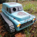
The core concept though is that they are quiet, safe to fly and yet still ridiculously acrobatic. This lends them to being thrown in you backpack to be flown wherever you find yourself, which is exactly what lead me to design this carry case. If you are into FPV and haven't tried this class of quad you really need to.
The other, unfortunate, characteristic of this class of quad is that they are quite breakable, especially if you are as talented as me at crashing into the hardest object in the park, which is what lead me to design a 3D-printable replacement frame. The quad I started with was the SailFlyX, so this frame is designed around those 1103 motors and their specific mounting holes. (micro review: It is crazy performance for the money, but a bit delicate). I will share editable files which you can customise,in case you have different electronics.
The end result, after a few iterations of design, was that I created a frame strong enough to result in me breaking motors instead... something I cant print replacements for... yet :-D
In the spirit of the "Make it Fly" contest I hope that these parts will help keep you in the air, and if I win the contest, get me back in the air too! So if you appreciate the work that goes into this stuff, please vote or consider leaving a tip on myminifactory towards my next broken quad:-D
If you would like to fine my work around the web, check out Patreon, Facebook page, Facebook group, Instagram, MyMiniFactory or Youtube
Supplies
STL Files for 3D Printing
Material
- Happy Model SailflyX or simlar "toothpick" quadcopter
- Filament, I'd recommend PLA or PETG (I used DavinciLabsZA PLA)
- Paint, if you feel like it
Tools
- Screwdriver
- Needle Files
Step 1: 3D Print a Replacement Frame


So if you broke your carbon fibre frame within a few flights, just like I did, you'll need a replacement. There is a lot of merit in a 3D printable frame in this class, since they are so small that you can print a new one in an hour or less.
Get the STLS
If you require a replacement frame, here is where you get my STL files on MyMinifactory
Printing: Material Choice
Some notes on material.
- I designed this with PLA in mind. Although it is not super strong it is stiff for the weight, a desirable feature. Mine has survived a number of crashes, including one that broke a motor shaft.
- You could use ABS, which if printed well should be tougher and far more impact resistant, but will not be as stiff. If printed poorly it's not strong due to poor inter-layer adhesion.
- PETG will be an interesting test, but my experiments have shown it to have poor impact strength and a tendency to shatter, as well as being too flexible.
- Nylon is tough but too flexible in this design (see my brushless whoop design instead)
- Carbon infused nylon (not PETG or PLA) such as rigid.ink's carbonyte would be the ultimate, but it is pricey and harder to print. In this case it would probably be worth reducing the frame to save weight since the strength is greater.
Printing: Support
None needed, just orient the frame with the "top" flat face down, and all will be well.
Step 2: Assemble Replacement


There is really not much to this, if you can take the parts of your broken frame you can put them straight onto the newly printed replacement.
I took significant care to ensure that there are no extra parts needed when swapping the SailflyX parts over, and there aren't likely to be any needed with most other donor quads either.
You will need a battery strap of sorts, such as the one included with the SailFlyX (see the pics)
Points to Keep in Mind
- Don't tug on the motor wires to remove the connectors, rather lever them out with tweezers or the tip of a sharp knife (don't cut your fingers off, unless you fly thumbs I guess, then don't cut your thumbs off)
- Use a needle file, or small drill bit, to clear out the motor screw holes on the frame so that the screws don't bind to the frame, it make assembly far easier.
- If you have added an external receiver then zip ties and heat shrink make great supports, or you can thread the antenna through the frame (see my photos)
Step 3: Designing and Customising the Printable Frame


Design Considerations
You may well decided that you want to design your own frame (I encourage it, it's quite rewarding!) in which case these are some design criteria that I followed. I recorded a few raw thoughts and notes during the process,which I have compiled into the following video, or you can read the notes below.
You will notice that I have "closed" all of the holes on the flat surface that will be on the print bed. Allowing the printer to try and outline all of the tiny holes on the first layer is a recipe for losing bed adhesion and resulting in a failed (or warped) print. By filling the holes with a 0.2mm thick "skin" the first layer is greatly simplified. This skin is easily poked through when it comes to installing the screws.
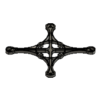
Designing a printable quadcopter frame is always a balancing act between weight and rigidity. Simply copying a design intended for carbon fibre will not be ideal. Rather use box structures (as seen in the arms of my design) to achieve the stiffness, without adding too much weight.
You will also notice that all of the thin vertical features, such as the vertical stiffening walls on the arms, are even multiples of 0.4mm. Assuming a 0.4mm print nozzle this will result in stronger cleaner extrusions than using, for example, a 1mm wall, which the slicer is likely to turn into two adjacent 0.4mm walls with a tiny, weak, gap between them.
Using gentle curves rather sharp corners also results in a stronger frame, since stresses from impact are not focused into one point.
I also took care to recess the screw heads in the frame, which has two benefits
- The screw heads will not poke into the battery as on the carbon frame.
- Though the printed frame is thicker the original screws can still be used.
Modify my Design
So this is where things get interesting.
If you need something different, perhaps you'd like to
- have shorter or longer arms?
- shave off some weight?
- add some stiffness?
- change the motor mounting pattern?
I have packaged up my design as to clean base features (attached to this step), which you can easily modify in Fusion360. If you do, please be sure to send me pics, I'd love to see them! Go ahead and share the files too (though I would appreciate accreditation with a link back here)

Step 4: Designing and Printing a Carry Case


Quadcopter Size
I designed this box to be useful across a range of toothpick-style quads as possible. In general if you have a brushless micro running 65mm (or even 3 inch) bi-blades it should fit.
The clips that hold the quadcopter down are wide to handle a variety of frames, and can clip at 3 different heights to handle a variety of frame thicknesses
Material
The walls of the case have been designed to be an even multiple of 0.4mm thick, in case you wish to print them solid. I printed my prototype with 0.8mm walls however and was so impressed by its strength that I didn't print another.
I printed mine in PLA, since i had it on hand and it makes printing the large flat base very easy (this could be prone to warping in ABS).
I actually think PETG is the right answer, for ease of printing and resistance to heat (such as if you were to leave it out in the sun while flying), but I only had enough of that left to do the clips (they work just fine in PLA too)
Step 5: Painting the Box


Now this step is not exactly necessary, unless you want to be cool, then it totally is ;-) I am no fancy painter unfortunately, so this is my rather rudimentary method.
Priming
I primed my PLA print with a generic plastic-primer in a rattle-can.
Depending on the kind of finish you are going for this is probably not even necessary. I was initially planning to do a hammered finish, but ran out of that.
Acrylic Base
I dabbed on thick acrylic hobby paint with a piece of sponge. The resulting stippled surface does a good job of hiding layer lines from the printing process.
I used black with a very very small amount of white in some places (to break up the monotony)
Spray
Once the acrylic was starting to dry I did a light dusting of white spray paint, which brought the whole thing to a sort of grey colour.
When the whole thing was properly dry I did a spatter coat of silver by doing short light presses on the can's nozzle, just to the point where the paint starts to come out in messy spurts.
Step 6: Other Printable Items


I have used 3D printing to repair and improve all kinds of things for micro quad-copters, here are some of the others, which you may find useful.
M2 Nut Driver
An item that I found was lacking in most RTF kits was an M2 nut driver, so I designed one that you can print
SMA Thumb Screws
SMA thumb screws are simple thumbscrews which can be used to loosen/tighten SMA connectors, as commonly used on FPV goggles. The slot allows it to be slipped over most cables, but there is a closed version too.
Replacement Frames for 75mm brushless Quadcopters
A replacement frame for the Snapper7 (or similar) Quadcopter (suitable for ABS, PC or perhaps PLA)
A replacement frame for the Snapper7 (or similar) Quadcopter suitable for Nylon (or perhaps PC). This is a fully printed frame, prop guard and camera mount for a 75mm brushless micro quad, designed to be light yet still stiff. Best printed in nylon
Camera mount (I think there are better ones, but I include it for reference)

Runner Up in the
Make It Fly Challenge


